Feb 10, 2018

what is Synchronous Condenser?

Synchronous Condenser

Section view showing interior construction of condenser 
A synchronous condenser (sometimes called a synchronous capacitor or synchronous compensator) is a DC-excited synchronous motor, whose shaft is not connected to anything but spins freely.[1] Its purpose is not to convert electric power to mechanical power or vice versa, but to adjust conditions on the electric power transmission grid. Its field is controlled by a voltage regulator to either generate or absorb reactive power as needed to adjust the grid's voltage, or to improve power factor. The condenser’s installation and operation are identical to large electric motors and generators.

Power in resistive and reactive AC circuits

Resistive and reactive AC circuits

Consider a circuit for a single-phase AC power system, where a 120 volt, 60 Hz AC voltage source is delivering power to a resistive load:

Feb 9, 2018

Standing waves and resonance/Transmission line-part F

Standing waves and resonance

Standing waves
Whenever there is a mismatch of impedance between transmission line and load, reflections will occur. If the incident signal is a continuous AC waveform, these reflections will mix with more of the oncoming incident waveform to produce stationary waveforms called standing waves.
The following illustration shows how a triangle-shaped incident waveform turns into a mirror-image reflection upon reaching the line's unterminated end. The transmission line in this illustrative sequence is shown as a single, thick line rather than a pair of wires, for simplicity's sake. The incident wave is shown traveling from left to right, while the reflected wave travels from right to left:

Feb 8, 2018

Wave guides/Transmission line-part-H

Wave-guides

A waveguide is a special form of transmission line consisting of a hollow, metal tube. The tube wall provides distributed inductance, while the empty space between the tube walls provide distributed capacitance:

Feb 7, 2018

Technology for Volt & Current: Working principal of Volt and Current in Measuring circuit

Technology for Volt & Current: Working principal of Volt and Current in Measuring circuit

Basic Concepts Of Electricity

Static Electricity

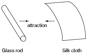
It was discovered centuries ago that certain types of materials would mysteriously attract one another after being rubbed together. For example: after rubbing a piece of silk against a piece of glass, the silk and glass would tend to stick together. Indeed, there was an attractive force that could be demonstrated even when the two materials were separated:

Working principal of Volt and Current in Measuring circuit

 Voltmeters and Ammeters

AC electromechanical meter movements come in two basic arrangements: those based on DC movement designs, and those engineered specifically for AC use. Permanent-magnet moving coil (PMMC) meter movements will not work correctly if directly connected to alternating current, because the direction of needle movement will change with each half-cycle of the AC. Permanent-magnet meter movements, like permanent-magnet motors, are devices whose motion depends on the polarity of the applied voltage (or, you can think of it in terms of the direction of the current).

Energy losses in Transformer

Transformer Energy losses


When transformers transfer power, they do so with a minimum of loss. As it was stated earlier, modern power transformer designs typically exceed 95% efficiency. It is good to know where some of this lost power goes, however, and what causes it to be lost.

Stepper Motor Interfacing with 8051 / 8951

Stepper Motor

•A stepper motor is a widely used device that translates electrical pulses into mechanical movement
•The stepper motor is used for position control in applications such as disk drivers, dot matrix printers, and robotics, etc.
•Every stepper motor has a permanent magnet rotor (also called the shaft) surrounded by a stator .

Feb 5, 2018

Proper Grounding of Instrument and Control Systems in Hazardous Locations-Part-A

Introduction
Part-A
Grounding is defined as electrical equipment connected directly to mother earth, or to some conducting body that serves in place of the earth, such as the steel frame of a plant and its earth mat or the hull of a ship or oil drilling platform. Proper grounding is an essential component for safely and reliably operating electrical systems. Improper grounding methodology has the potential to bring disastrous results from both an operational as well as a safety standpoint. There are many different categories and types of grounding principles. This paper’s primary focus is to demonstrate proper grounding techniques for low voltage Instrument and Control Systems (IACS) that have been proven safe and reliable when employed in process control facilities. For the purposes of this paper, IACS will be defined as instrument and control systems that operate at 50 VDC or less. As an example of a typical plant, some of the accompanying photographs are courtesy of Washington Gas’ facilities in the metropolitan District of Colombia, Virginia and Maryland area as shown in Figure 1

Distributed Generator System Synchronization

 Synchronization

Distributed Redundant is a common UPS system design used in the market today. This design uses multiple UPS modules that have their output buses cross-connected for multiple power sources to the critical load by static transfer switches. Each static transfer switch will have two inputs. One input will be set as the primary feed for the switch. The other input will be set as the secondary. In the event of a power failure on the primary input of the static transfer switch, it will automatically switch to the secondary source. The switching action is a short duration open transition, typically up to 4ms. The primary and secondary inputs of all the switches will be divided among the outputs of the UPS modules. This is done so that the load is balanced across the entire system. If any one UPS module
were to fail, the static transfer switches that have their primary input fed by the failed UPS will switch input sources. The critical load is then transferred to the outputs of the other good UPS modules. Correct system design will ensure that the remaining good modules will not be overloaded at this time. Both inputs to the static transfer switches must be synchronized to minimize voltage transients during switching.

Concept of Alkaline Batteries

Alkaline Batteries

The world of storage power with Batteries have become one of the most important and most

Feb 3, 2018

Protection against over voltage Q & A- PART-A

Protection against over voltage 

1. Why protection of transmission line important?
It is essential for electrical power engineers to reduce the number of outages and preserve the
continuity of service and electric supply.

2. What are the causes of over voltages in electric system?

 External Cause – Lightning
 Internal Cause – Switching

3. What are the causes of power frequency over voltages?

Feb 2, 2018

Concept of Stepper motors

Stepper motors

A stepper motor is a "digital" version of the electric motor. The rotor moves in discrete steps as commanded, rather than rotating continuously like a conventional motor. When stopped but energized, a stepper (short for stepper motor) holds its load steady with a holding torque. Wide spread acceptance of the stepper motor within the last two decades was driven by the ascendancy of digital electronics. Modern solid state driver electronics was a key to its success. And, microprocessors readily interface to stepper motor driver circuits.

Concept of AC Bridge Circuits

AC Bridge Circuits


As we saw with DC measurement circuits, the circuit configuration known as a bridge can be a very useful way to measure unknown values of resistance. This is true with AC as well, and we can apply the very same principle to the accurate measurement of unknown impedance. To review, the bridge circuit works as a pair of two-component voltage dividers connected across the same source voltage, with a null-detector meter movement connected between them to indicate a condition of “balance” at zero volts: (Figure below)

A balanced bridge shows a “null”, or minimum reading, on the indicator.

Synchronous generator interview questions with answer

 Interview questions with answer 


Q:Why syn. generators are used for the production of electricity?


Introduction of Gas Turbine Power Plant

Gas Turbine Power Plant


An internal combustion engine in which expanding gases from the combustion

Feb 1, 2018

Long and Short Transmission Lines-Transmission line PART-E

Long and Short Transmission Lines

In DC and low-frequency AC circuits, the characteristic impedance of parallel wires is usually ignored. This includes the use of coaxial cables in instrument circuits, often employed to protect weak voltage signals from being corrupted by induced "noise" caused by stray electric and magnetic fields. This is due to the relatively short time spans in which reflections take place in the line, as compared to the period of the waveform or pulses of the significant signals in the circuit. As we saw in the last section, if a transmission line is connected to a DC voltage source, it will behave as a resistor equal in value to the line's characteristic impedance only for as long as it takes the incident pulse to reach the end of the line and return as a reflected pulse, back to the source. After that time (a brief 16.292 μs for the mile-long coaxial cable of the last example), the source "sees" only the terminating impedance, whatever that may be.

If the circuit in question handles low-frequency AC power, such short time delays introduced by a transmission line between when the AC source outputs a voltage peak and when the source "sees" that peak loaded by the terminating impedance (round-trip time for the incident wave to reach the line's end and reflect back to the source) are of little consequence. Even though we know that signal magnitudes along the line's length are not equal at any given time due to signal propagation at (nearly) the speed of light, the actual phase difference between start-of-line and end-of-line signals is negligible, because line-length propagation occur within a very small fraction of the AC waveform's period. For all practical purposes, we can say that voltage along all respective points on a low-frequency, two-conductor line are equal and in-phase with each other at any given point in time.

In these cases, we can say that the transmission lines in question are electrically short, because their propagation effects are much quicker than the periods of the conducted signals. By contrast, an electrically long line is one where the propagation time is a large fraction or even a multiple of the signal period. A "long" line is generally considered to be one where the source's signal waveform completes at least a quarter-cycle (90o of "rotation") before the incident signal reaches line's end. Up until this chapter in the Lessons In Electric Circuits book series, all connecting lines were assumed to be electrically short.

To put this into perspective, we need to express the distance traveled by a voltage or current signal along a transmission line in relation to its source frequency. An AC waveform with a frequency of 60 Hz completes one cycle in 16.66 ms. At light speed (186,000 m/s), this equates to a distance of 3100 miles that a voltage or current signal will propagate in that time. If the velocity factor of the transmission line is less than 1, the propagation velocity will be less than 186,000 miles per second, and the distance less by the same factor. But even if we used the coaxial cable's velocity factor from the last example (0.66), the distance is still a very long 2046 miles! Whatever distance we calculate for a given frequency is called the wavelength of the signal.

The lower-case Greek letter "lambda" (λ) represents wavelength, in whatever unit of length used in the velocity figure (if miles per second, then wavelength in miles; if meters per second, then wavelength in meters). Velocity of propagation is usually the speed of light when calculating signal wavelength in open air or in a vacuum, but will be less if the transmission line has a velocity factor less than 1.

If a "long" line is considered to be one at least 1/4 wavelength in length, you can see why all connecting lines in the circuits discussed thusfar have been assumed "short." For a 60 Hz AC power system, power lines would have to exceed 775 miles in length before the effects of propagation time became significant. Cables connecting an audio amplifier to speakers would have to be over 4.65 miles in length before line reflections would significantly impact a 10 kHz audio signal!

When dealing with radio-frequency systems, though, transmission line length is far from trivial. Consider a 100 MHz radio signal: its wavelength is a mere 9.8202 feet, even at the full propagation velocity of light (186,000 m/s). A transmission line carrying this signal would not have to be more than about 2-1/2 feet in length to be considered "long!" With a cable velocity factor of 0.66, this critical length shrinks to 1.62 feet.

When an electrical source is connected to a load via a "short" transmission line, the load's impedance dominates the circuit. This is to say, when the line is short, its own characteristic impedance is of little consequence to the circuit's behavior. We see this when testing a coaxial cable with an ohmmeter: the cable reads "open" from center conductor to outer conductor if the cable end is left unterminated. Though the line acts as a resistor for a very brief period of time after the meter is connected (about 50 Ω for an RG-58/U cable), it immediately thereafter behaves as a simple "open circuit:" the impedance of the line's open end. Since the combined response time of an ohmmeter and the human being using it greatly exceeds the round-trip propagation time up and down the cable, it is "electrically short" for this application, and we only register the terminating (load) impedance. It is the extreme speed of the propagated signal that makes us unable to detect the cable's 50 Ω transient impedance with an ohmmeter.

If we use a coaxial cable to conduct a DC voltage or current to a load, and no component in the circuit is capable of measuring or responding quickly enough to "notice" a reflected wave, the cable is considered "electrically short" and its impedance is irrelevant to circuit function. Note how the electrical "shortness" of a cable is relative to the application: in a DC circuit where voltage and current values change slowly, nearly any physical length of cable would be considered "short" from the standpoint of characteristic impedance and reflected waves. Taking the same length of cable, though, and using it to conduct a high-frequency AC signal could result in a vastly different assessment of that cable's "shortness!"

When a source is connected to a load via a "long" transmission line, the line's own characteristic impedance dominates over load impedance in determining circuit behavior. In other words, an electrically "long" line acts as the principal component in the circuit, its own characteristics overshadowing the load's. With a source connected to one end of the cable and a load to the other, current drawn from the source is a function primarily of the line and not the load. This is increasingly true the longer the transmission line is. Consider our hypothetical 50 Ω cable of infinite length, surely the ultimate example of a "long" transmission line: no matter what kind of load we connect to one end of this line, the source (connected to the other end) will only see 50 Ω of impedance, because the line's infinite length prevents the signal from ever reaching the end where the load is connected. In this scenario, line impedance exclusively defines circuit behavior, rendering the load completely irrelevant.

The most effective way to minimize the impact of transmission line length on circuit behavior is to match the line's characteristic impedance to the load impedance. If the load impedance is equal to the line impedance, then anysignal source connected to the other end of the line will "see" the exact same impedance, and will have the exact same amount of current drawn from it, regardless of line length. In this condition of perfect impedance matching, line length only affects the amount of time delay from signal departure at the source to signal arrival at the load. However, perfect matching of line and load impedance is not always practical or possible.

The next section discusses the effects of "long" transmission lines, especially when line length happens to match specific fractions or multiples of signal wavelength.
Review

Coaxial cabling is sometimes used in DC and low-frequency AC circuits as well as in high-frequency circuits, for the excellent immunity to induced "noise" that it provides for signals. 

When the period of a transmitted voltage or current signal greatly exceeds the propagation time for a transmission line, the line is considered electrically short. Conversely, when the propagation time is a large fraction or multiple of the signal's period, the line is considered electrically long. 

A signal's wavelength is the physical distance it will propagate in the time span of one period. 

Wavelength is calculated by the formula λ=v/f, where "λ" is the wavelength, "v" is the propagation velocity, and "f" is the signal frequency. 

A rule-of-thumb for transmission line "shortness" is that the line must be at least 1/4 wavelength before it is considered "long." 

In a circuit with a "short" line, the terminating (load) impedance dominates circuit behavior. The source effectively sees nothing but the load's impedance, barring any resistive losses in the transmission line. 

In a circuit with a "long" line, the line's own characteristic impedance dominates circuit behavior. The ultimate example of this is a transmission line of infinite length: since the signal will never reach the load impedance, the source only "sees" the cable's characteristic impedance. 

When a transmission line is terminated by a load precisely matching its impedance, there are no reflected waves and thus no problems with line length.

Read More About

Circuit Schematic Symbols

Transmission line- 50-Ohm Cable- Part-A

Transmission line-Circuits and the speed of light-Part-B

Transmission line-Characteristic impedance-part-c

Finite-length transmission lines-Part-D

Jan 30, 2018

Concept of Wound rotor induction motors

Wound rotor induction motors

A wound rotor induction motor has a stater like the squirrel cage induction motor, but a rotor with insulated winding brought out via slip rings and brushes. However, no power is applied to the slip rings. Their sole purpose is to allow resistance to be placed in series with the rotor winding while starting. This resistance is shorted out once the motor is started to make the rotor look electrically like the squirrel cage counterpart.

Search This Blog