
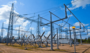
Electrical Substation
The electricity substation is a network of electrical equipment which is connected in a structured way in order to supply electricity to end consumers. There is numerous electrical substation components like outgoing and incoming circuitry each of which having its circuit breakers, isolators, transformers, and busbar system etc for the smooth functioning of the system. The power system is having numerous ingredients such as distribution, transmission, and generation systems and Substations act as a necessary ingredient for operations of the power system. The substations are entities from which consumers are getting their electrical supply to run their loads while required power quality can be delivered to the customers by changing frequency and voltage levels etc..
The electricity substation designs are purely dependent on the need, for instance, a single bus or complex bus system etc. Moreover, the design is also dependent on the application as well, for instance, indoor substations, generation substations, transmission substations, pole substations, outdoor substation, converter substation, and switching substation etc. There is a need of collector substation as well in cases of large power generating systems e.g. multiple thermal and hydropower plants connected together for transfer of power to a single transmission unit from numerous co-located turbines.
The following are major electrical components of substations and their working. Each component functions are explained in detail with machinery, substation components diagram is also given above for your reference.
List of Electrical Substation Equipment :
- Instrument Transformers
- Current Transformer
- Potential Transformer
- Conductors
- Insulators
- Isolators
- Busbars
- Lightning Arrestors
- Circuit Breakers
- Relays
- Capacitor Banks
- Batteries
- WaveTrapper
- SwitchYard
- Metering and Indication Instruments
- Equipment for Carrier Current
- Prevention from Surge Voltage
- The Outgoing Feeders
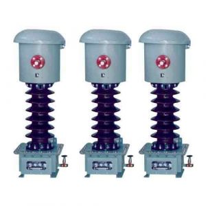
Instrument Transformers:
The instrument transformer is a static device utilized for reduction of higher currents and voltages for safe and practical usage which are measurable with traditional instruments such as digital multi-meter etc. The value range is from 1A to 5A and voltages such as 110V etc. The transformers are also used for actuation of AC protective relay through supporting voltage and current. Instrument transformers are shown in the figure below and its two types are also discussed underneath.
Instrument transformers
Current Transformer:
A current transformer is a gadget utilized for the transformation of higher value currents into lower values. It is utilized in an analogous manner to that of AC instruments, control apparatus, and meters. These are having lower current ratings and are used for maintenance and installation of current relays for protection purpose in substations.
Current Transformer
Potential Transformer:
The potential transformers are similar in characteristics as current transformers but are utilized for converting high voltages to lower voltages for protection of relay system and for lower rating metering of voltage measurements.
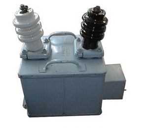
Potential Transformer
Conductors:
Conductors are the materials which permit flow of electrons through it. The best conductors are copper and aluminum etc. The conductors are utilized for transmission of energy from place to place over substations.
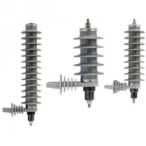
Insulators:
The insulators are the materials which do not permit flow of electrons through it. Insulators are resisting electric property. There are numerous types of insulators such as shackle, strain type, suspension type, and stray type etc. Insulators are used in substations for avoiding contact with humans or short circuit.
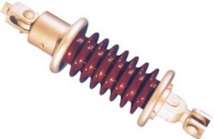
Insulator
Isolators:
The isolators in substations are mechanical switches which are deployed for isolation of circuits when there is an interruption of current. These are also known with the name of disconnected switches operation under no-load conditions and are not fortified with arc-quenching devices. These switches have no specific current breaking value neither these have current making value. These are mechanically operated switches.
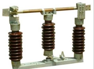
Isolator
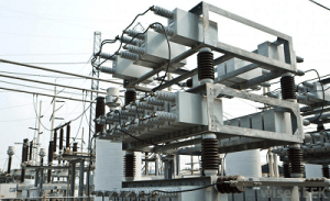
Busbars:
The busbar is among the most important elements of the substation and is a conductor which carries current to a point having numerous connections with it. The busbar is a kind of electrical junction which has outgoing and incoming current paths. Whenever a fault occurs in the busbar, entire components connected to that specific section should be tripped for giving thorough isolation in a small time, for instance, 60ms for avoiding danger rising due to conductor’s heat. These are of different types such as ring bus, double bus, and single bus etc. A simple bus bar is shown in the figure below which is considered as one of the most vital electrical substation components.
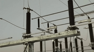
Busbar in Substation
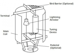
The Lightning Arresters:
The lightning arresters can be considered as the first ever components of a substation. These are having a function of protecting equipment of substation from high voltages and are also limiting the amplitude and duration of the current’s flow. These are connected amid earth and line i.e. connected in line with equipment in the substation. These are meant for diversion of current to earth if any current surge appears hence by protecting insulation as well as conductor from damages. These are of various types and are distinguished based on duties.
Lightning Arrester
Circuit Breakers:
The circuit breakers are such type of switches utilized for closing or opening circuits at the time when a fault occurs within the system. The circuit breaker has 2 mobile contacts which are in OFF condition in normal situations. At the time when any fault occurs in the system, a relay is sending the tripped command to the circuit breaker which moves the contacts apart, hence avoiding any damage to the circuitry.
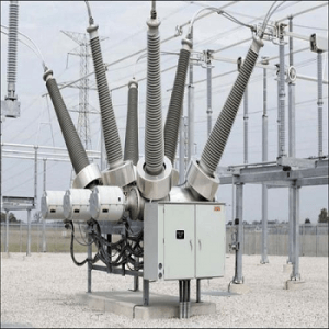
Circuit Breaker in Substation
Relays:
Relays are a dedicated component of electrical substation equipment for the protection of system against abnormal situations e.g. faults. Relays are basically sensing gadgets which are devoted for sensing faults and are determining its location as well as sending interruption message of tripped command to the specific point of the circuit. A circuit breaker is falling apart its contacts after getting the command from relays. These are protecting equipment from other damages as well such as fire, the risk to human life, and removal of fault from a particular section of the substation. Following is the substation component diagram is known as a relay.
Relays
Capacitor Banks:
The capacitor bank is defined as a set of numerous identical capacitors which are connected either in parallel or series inside an enclosure and are utilized for the correction of power factor as well as protection of circuitry of the substation. These are acting like the source of reactive power and are thus reducing phase difference amid current and voltage. These are increasing the capacity of ripple current of supply and avoid unwanted selves in the substation system. The use of capacitor banks is an economical technique for power factor maintenance and for correction of problems related to power lag.
Capacitor Bank in Substation
Batteries:
Some of the important substation parts such as emergency lighting, relay system, and automated control circuitry are operated through batteries. The size of the battery bank is depending on the voltage required for operation of the DC circuit respectively. The storage batteries are of two basic types i.e. acid-alkaline batteries and lead-acid batteries. The lead acid batteries are of the most common type and used in substations in abundance as these provide high voltages and are cheaper in cost.
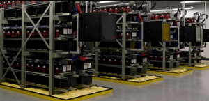
Substation Batteries
Wave Trapper:
The wave trapper is one of the substation components which is placed on the incoming lines for trapping of high-frequency waves. The high-frequency waves which are coming from nearby substations or other localities are disturbing the current and voltages, hence its trapping is of great importance. The wave trapper is basically tripping high-frequency waves and is then diverting the waves into telecom panel.
Wave Trapper in Substation
Switchyard:
The switchyards, switches, circuit breakers, and transformers for the connection and disconnection of transformers and circuit breakers. These are also having lighting arrestors to protect the substation or power station from strokes of natural lighting.
SwitchYard
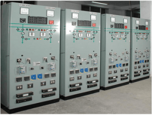
Metering and Indication Instruments:
There are numerous instruments for metering and indication in each substation such as watt-meters, voltmeters, ammeters, power factor meters, kWh meters, volt-ampere meters, and KVARH meters etc. These instruments are installed at different places within substation for controlling and maintaining values of current and voltages. For instance, 33/11KV substation equipment will comprise digital multi-meters for various readings of currents and voltages.
Equipment for Carrier Current:
The equipment of carrier current is installed in the substation for the purpose of communication, supervisory control, telemetry, and/or relaying etc. Such equipment is often mounted on a room which is known as carrier room and is connected across the power circuit of high voltages.
Prevention from Surge Voltage:
The transient of overvoltages substation system is because of inherent and natural characteristics. There are several reasons for overvoltages which may be caused due to a sudden alteration in conditions of the system e.g. load rejection, faults, or switching operations etc. or because of lighting etc. The types of overvoltages can be classified into two i.e. switching generated or lightning generated. However, the scale of overvoltages could be over maximum allowable voltage levels, hence these are required to be protected and reduced for avoiding damage to instruments, equipment, and lines of a substation. In this way, the performance of the substation system can be enhanced.
The Outgoing Feeders:
There are numerous outgoing feeders which are connected to that of substations. Basically, the connection is with a bus of the substation for carrying power from the substation to service points. The feeders can hug overhead streets, underground, underneath streets, and are carrying electrical power to that of distribution transformers at near or farther premises. The isolator in substation and breaker of the feeder are considered as entities of the substation and are of metal-clad typically. Whenever a fault is occurring in the feeder, the protection is detecting and the circuit breaker is opened. After detection of fault through manual or automatic way, there are more than one attempts for re-energizing the feeder.
Elements of a Substation
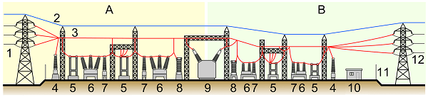
Elements of a substation A: Primary power lines’ side B: Secondary power lines’ side
- Primary power lines
- Ground wire
- Overhead lines
- Transformer for measurement of electric voltage
- Disconnect switch
- Circuit breaker
- Current transformer
- Lightning arrester
- Main transformer
- Control building
- Security fence
- Secondary power lines
While the above are some standard components that are seen in the electrical substations, depending upon the type of substation and their functioning the electrical substation components may slightly change. Also with the advancements in the technology many components are constantly upgraded to keep with the latest advancements to deliver constant power output.


 Mercury standard cells were also susceptible to slight changes in voltage if physically or thermally disturbed. Two different types of mercury standard cells were developed for different calibration purposes: saturated and unsaturated. Saturated standard cells provided the greatest voltage stability over time, at the expense of thermal instability. In other words, their voltage drifted very little with the passage of time (just a few microvolts over the span of a decade!), but tended to vary with changes in temperature (tens of microvolts per degree Celsius). These cells functioned best in temperature-controlled laboratory environments where long-term stability is paramount. Unsaturated cells provided thermal stability at the expense of stability over time, the voltage remaining virtually constant with changes in temperature but decreasing steadily by about 100 μV every year. These cells functioned best as "field" calibration devices where ambient temperature is not precisely controlled. Nominal voltage for a saturated cell was 1.0186 volts, and 1.019 volts for an unsaturated cell.
 Specific cost of solar cell technology (dollars per kilowatt) is still high but is constantly approaching the costs of electricity from the power grid. Unlike electronic components made from semiconductor material, which can be made smaller and smaller with less scrap as a result of better quality control, a single solar cell still takes the same amount of ultra-pure silicon to make as it did thirty years ago. Superior quality control fails to yield the same production gain seen in the manufacture of chips and transistors (where isolated specks of impurity can ruin many microscopic circuits on one wafer of silicon). The same number of impure inclusions does little to impact the overall efficiency of a 3-inch solar cell.
  Solar cells are often electrically connected and encapsulated as a module. PV modules often have a sheet of glass on the front (sun up) side , allowing light to pass while protecting the semiconductor wafers from the elements (rain, hail, etc.). Solar cells are also usually connected in series in modules, creating an additive voltage. Connecting cells in parallel will yield a higher current. Modules are then interconnected, in series or parallel, or both, to create an array with the desired peak DC voltage and current.
 To date, the most successful fuel cells constructed are those which run on hydrogen and oxygen, although much research has been done on cells using hydrocarbon fuels. While "burning" hydrogen, a fuel cell's only waste byproducts are water and a small amount of heat. When operating on carbon-containing fuels, carbon dioxide is also released as a byproduct. Because the operating temperature of modern fuel cells is far below that of normal combustion, no oxides of nitrogen (NOx) are formed, making it far less polluting, all other factors being equal.