New Year: नए साल पर करियर में लाना है बदलाव तो जरूर ध्यान में रखें ये बातें
तेजी से बदलते इस दौर में खुद को ढालने के लिए अपने स्किल्स पर लगातार काम करते रहना चाहिए.


NOTES&BOOKS For Electrical,Instruments,Automation,Travel & Mind tools


| Setting | Adjustment | Protection For |
| Ir | Long time Pick up Current Setting (or thermal Setting). This is a multiplication coefficient of the rating of the device. (Ir=xIn) | Protection against overloads |
| tr | Long time delay Setting in seconds, enabling in particular the starting current of a motor to be tolerated. (tr=Sec) | Protection against overloads |
| Im / Isd | Short time (Magnetic Setting). This is a multiplier of the Ir setting, often 1.5 to 10 times the Ir current (im=xIr) | Protection against short circuits. |
| tm / tsd | Short time delay Setting, enabling in particular the discrimination (time) to be increased with downstream feeders and the magnetization peaks of a transformer or a motor to be tolerated. It is recommended that the I²t selector switch is set to the ON position.(tm=Sec) | Protection against short circuits. |
| Ii | Instantaneous current Setting. Protecting the installation against strong short circuits (dead short circuits) by instantaneous tripping without Time Delay and self-protection of the circuit breaker.
The Ii > Isd.
| Protection against Dead Short circuits. |
| Ig | for monitoring the earth fault current circulating in the Phase and Earth conductor in TNS systems | Earth protection |
| tg | Earth protection time delay | Earth protection |
| I delta n | Adjustment of the sensitivity of the earth leakage protection | Earth leakage protection |
| delta t | Earth leakage protection delay. | Earth leakage protection |


| Lighting Source CCT | |
| Source | Color temperature in Kelvin |
| Skylight (blue sky) | 12,000 – 20,000 |
| Average summer shade | 8000 |
| Light summer shade | 7100 |
| Typical summer light (sun + sky) | 6500 |
| Daylight fluorescent | 6300 |
| Xenon short-arc | 6400 |
| Overcast sky | 6000 |
| Clear mercury lamp | 5900 |
| Sunlight (noon, summer, mid-latitudes) | 5400 |
| Design white fluorescent | 5200 |
| Special fluorescents used for color evaluation | 5000 |
| Daylight photoflood | 4800 – 5000 |
| Sunlight (early morning and late afternoon) | 4300 |
| Brite White Deluxe Mercury lamp | 4000 |
| Sunlight (1 hour after dawn) | 3500 |
| Cool white fluorescent | 3400 |
| Photoflood | 3400 |
| Professional tungsten photographic lights | 3200 |
| 100-watt tungsten halogen | 3000 |
| Deluxe Warm White fluorescent | 2950 |
| 100-watt incandescent | 2870 |
| 40-watt incandescent | 2500 |
| High-pressure sodium light | 2100 |
| Sunlight (sunrise or sunset) | 2000 |
| Candle flame | 1850 – 1900 |
| Match flame | 1700 |
| Skylight (blue sky) | 12,000 – 20,000 |
| Average summer shade | 8000 |
| Light summer shade | 7100 |
| Typical summer light (sun + sky) | 6500 |
| Daylight fluorescent | 6300 |
| Xenon short-arc | 6400 |
| Overcast sky | 6000 |
| Clear mercury lamp | 5900 |
| Sunlight (noon, summer, mid-latitudes) | 5400 |
| Design white fluorescent | 5200 |
| Special fluorescents used for color evaluation | 5000 |
| Daylight photoflood | 4800 – 5000 |
| Sunlight (early morning and late afternoon) | 4300 |
| Bright White Deluxe Mercury lamp | 4000 |
| Sunlight (1 hour after dawn) | 3500 |
| Cool white fluorescent | 3400 |
| Photoflood | 3400 |
| Professional tungsten photographic lights | 3200 |
| 100-watt tungsten halogen | 3000 |
| Deluxe Warm White fluorescent | 2950 |
| 100-watt incandescent | 2870 |
| 40-watt incandescent | 2500 |
| High-pressure sodium light | 2100 |
| Sunlight (sunrise or sunset) | 2000 |
| Candle flame | 1850 – 1900 |
| Match flame | 1700 |

CCT – Correlated Color Temperature
| |||
| Kelvin | Associated Effects | Type of Bulbs | Appropriate Applications |
| 2700° | Warm White, Very Warm White | incandescent bulbs | Homes, Libraries, Restaurants |
| 3000° | Warm White | most halogen lamps, Slightly ‘whiter’ than ordinary incandescent lamps | Homes, Hotel rooms and Lobbies, Restaurants, retail Stores |
| 3500° | White | Fluorescent or CFL | Executive offices, public reception areas, supermarkets |
| 4100° | Cool White | Office, classrooms, mass merchandisers, showrooms | |
| 5000° | Daylight | Fluorescent or CFL | Graphic industry, hospitals |
| 6500° | Cool Daylight | Extremely ‘white’ | Jewelry stores, beauty salons, galleries, museums, printing |
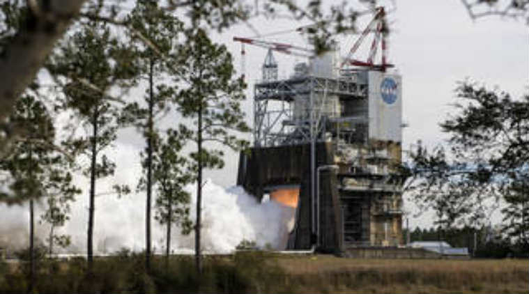 The test was part of the SLS Programme’s RS-25 affordability initiative – a collaborative effort between NASA and industry partner Aerojet Rocketdyne of Canoga Park, California. (Image Source: NASA)