Feb 10, 2018

what is Synchronous Condenser?

Synchronous Condenser

Section view showing interior construction of condenser 
synchronous condenser (sometimes called a synchronous capacitor or synchronous compensator) is a DC-excited synchronous motor, whose shaft is not connected to anything but spins freely.[1] Its purpose is not to convert electric power to mechanical power or vice versa, but to adjust conditions on the electric power transmission grid. Its field is controlled by a voltage regulator to either generate or absorb reactive power as needed to adjust the grid's voltage, or to improve power factor. The condenser’s installation and operation are identical to large electric motors and generators.

Power in resistive and reactive AC circuits

Resistive and reactive AC circuits

Consider a circuit for a single-phase AC power system, where a 120 volt, 60 Hz AC voltage source is delivering power to a resistive load:

Feb 9, 2018

Standing waves and resonance/Transmission line-part F

Standing waves and resonance

Standing waves
Whenever there is a mismatch of impedance between transmission line and load, reflections will occur. If the incident signal is a continuous AC waveform, these reflections will mix with more of the oncoming incident waveform to produce stationary waveforms called standing waves.
The following illustration shows how a triangle-shaped incident waveform turns into a mirror-image reflection upon reaching the line's unterminated end. The transmission line in this illustrative sequence is shown as a single, thick line rather than a pair of wires, for simplicity's sake. The incident wave is shown traveling from left to right, while the reflected wave travels from right to left:

Feb 8, 2018

Wave guides/Transmission line-part-H

Wave-guides

waveguide is a special form of transmission line consisting of a hollow, metal tube. The tube wall provides distributed inductance, while the empty space between the tube walls provide distributed capacitance:

Feb 7, 2018

Technology for Volt & Current: Working principal of Volt and Current in Measuring circuit

Technology for Volt & Current: Working principal of Volt and Current in Measuring circuit

Basic Concepts Of Electricity

Static Electricity

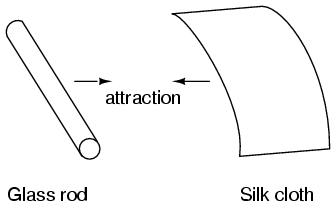
It was discovered centuries ago that certain types of materials would mysteriously attract one another after being rubbed together. For example: after rubbing a piece of silk against a piece of glass, the silk and glass would tend to stick together. Indeed, there was an attractive force that could be demonstrated even when the two materials were separated:

Working principal of Volt and Current in Measuring circuit

 Voltmeters and Ammeters

AC electromechanical meter movements come in two basic arrangements: those based on DC movement designs, and those engineered specifically for AC use. Permanent-magnet moving coil (PMMC) meter movements will not work correctly if directly connected to alternating current, because the direction of needle movement will change with each half-cycle of the AC. Permanent-magnet meter movements, like permanent-magnet motors, are devices whose motion depends on the polarity of the applied voltage (or, you can think of it in terms of the direction of the current).

Energy losses in Transformer

Transformer Energy losses


When transformers transfer power, they do so with a minimum of loss. As it was stated earlier, modern power transformer designs typically exceed 95% efficiency. It is good to know where some of this lost power goes, however, and what causes it to be lost.

Stepper Motor Interfacing with 8051 / 8951

Stepper Motor

•A stepper motor is a widely used device that translates electrical pulses into mechanical movement
•The stepper motor is used for position control in applications such as disk drivers, dot matrix printers, and robotics, etc.
•Every stepper motor has a permanent magnet rotor (also called the shaft) surrounded by a stator .

Feb 5, 2018

Proper Grounding of Instrument and Control Systems in Hazardous Locations-Part-A

Introduction
Part-A
Grounding is defined as electrical equipment connected directly to mother earth, or to some conducting body that serves in place of the earth, such as the steel frame of a plant and its earth mat or the hull of a ship or oil drilling platform. Proper grounding is an essential component for safely and reliably operating electrical systems. Improper grounding methodology has the potential to bring disastrous results from both an operational as well as a safety standpoint. There are many different categories and types of grounding principles. This paper’s primary focus is to demonstrate proper grounding techniques for low voltage Instrument and Control Systems (IACS) that have been proven safe and reliable when employed in process control facilities. For the purposes of this paper, IACS will be defined as instrument and control systems that operate at 50 VDC or less. As an example of a typical plant, some of the accompanying photographs are courtesy of Washington Gas’ facilities in the metropolitan District of Colombia, Virginia and Maryland area as shown in Figure 1

Distributed Generator System Synchronization

 Synchronization

Distributed Redundant is a common UPS system design used in the market today. This design uses multiple UPS modules that have their output buses cross-connected for multiple power sources to the critical load by static transfer switches. Each static transfer switch will have two inputs. One input will be set as the primary feed for the switch. The other input will be set as the secondary. In the event of a power failure on the primary input of the static transfer switch, it will automatically switch to the secondary source. The switching action is a short duration open transition, typically up to 4ms. The primary and secondary inputs of all the switches will be divided among the outputs of the UPS modules. This is done so that the load is balanced across the entire system. If any one UPS module
were to fail, the static transfer switches that have their primary input fed by the failed UPS will switch input sources. The critical load is then transferred to the outputs of the other good UPS modules. Correct system design will ensure that the remaining good modules will not be overloaded at this time. Both inputs to the static transfer switches must be synchronized to minimize voltage transients during switching.

Concept of Alkaline Batteries

Alkaline Batteries

The world of storage power with Batteries have become one of the most important and most

Search This Blog