Dec 25, 2017

What is Distributed Control System DCS?

 Distributed Control System

In recent years, the use of smart devices and field buses makes distributed control system (DCS) to be prominent in large and complex industrial processes as compared to the former centralized control system. This distribution of control system architecture around the plant has led to produce more efficient ways to improve reliability of control, process quality and plant efficiency.
Nowadays, distributed control system has been found in many industrial fields such as chemical plants, oil and gas industries, food processing units, nuclear power plants, water management systems, automobile industries, etc.

What is Distributed Control System DSC

What is DCS System?

distributed control system (DCS) is a specially designed automated control system that consists of geographically distributed control elements over the plant or control area.

It differs from the centralized control system wherein a single controller at central location handles the control function, but in DCS each process element or machine or group of machines is controlled by a dedicated controller. DCS consists of a large number of local controllers in various sections of plant control area and are connected via a high speed communication network.

What is Distributed Control System (DCS)

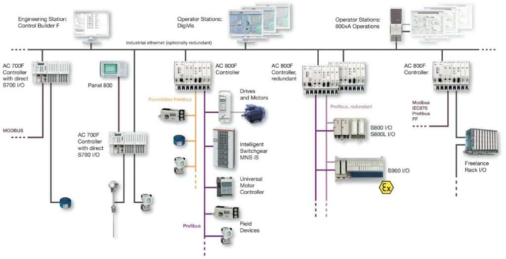
In DCS control system, data acquisition and control functions are carried through a number of DCS controllers which are microprocessor based units distributed functionally and geographically over the plant and are situated near area where control or data gathering functions being performed as shown in the figure above. These controllers able to communicate among themselves and also with other controllers like supervisory terminals, operator terminals, historians, etc.
Distributed individual automatic controllers are connected to field devices such as sensors and actuators. These controllers ensure the sharing of gathered data to other hierarchal controllers via different field buses. Different field buses or standard communication protocols are used for establishing the communication between the controllers. Some of these include Profibus, HART, arc net, Modbus, etc.
DCS is most suited for large-scale processing or manufacturing plants wherein a large number of continuous control loops are to be monitored and controlled. The main advantage of dividing control tasks for distributed controllers is that if any part of DCS fails, the plant can continue to operate irrespective of failed section.

Architecture of Distributed Control System

As the name suggests, DCS has three main qualities. The first one is the distribution of various control functions into relatively small sets of subsystems, which are of semiautonomous, and are interconnected through a high speed communication bus. Some of these functions include data acquisition, data presentation, process control, process supervision, reporting information, storing and retrieval of information.
The second attribute of DCS is the automation of manufacturing process by integrating advanced control strategies. And the third characteristic is the arranging the things as a system. DCS organizes the entire control structure as a single automation system where various subsystems are unified through a proper command structure and information flow.

These attributes of DCS can be observed in its architecture shown in the diagram below. The basic elements comprised in a DCS include engineering workstation, operating station or HMI, process control unit or local control unit, smart devices, and communication system.

Architecture of DCS

Engineering Workstation:

It is the supervisory controller over the entire distributed control system. It can be a PC or any other computer that has dedicated engineering software (for example, control builder F engineering station in case of ABB freelance distributed control system).
This engineering station offers powerful configuration tools that allow the user to perform engineering functions such as creating new loops, creating various input and output points, modifying sequential and continuous control logic, configuring various distributed devices, preparing documentation for each input/output device, etc.

Operating Station or HMI

This is used to operate, monitor and control plant parameters. It can be a PC or any other monitoring device that has a separate software tool on which operator can view process parameter values and accordingly to take control action. For instance, it is a DigiVis software tool that can run on a simple PC-environment in case ABB DCS.
Operating stations can be a single unit or multiple units where a single unit performs functions like parameter value display, trend display, alarming, etc. while multiple units or PCs performs individual functions such as some PCs display parameters, some for trend archives, some for data logging and acquiring, etc.Operating station of DCS (Distributed Control System)

Process Control Unit of DCS

It is also called as a local control unit, distribution controller, or process station. A distributed control system can consists of one or more process stations that can be extended with different types of I/O units. These controllers consist of a powerful CPU module, field bus or communication module with extended field bus capability and either direct or remote connected I/Os.
The field devices like sensors and actuators are connected to I/O modules of this unit. Some field devices can be directly connected to field bus (such as Profibus) without any I/O module, which can be termed as smart field devices.Distribution Control unit
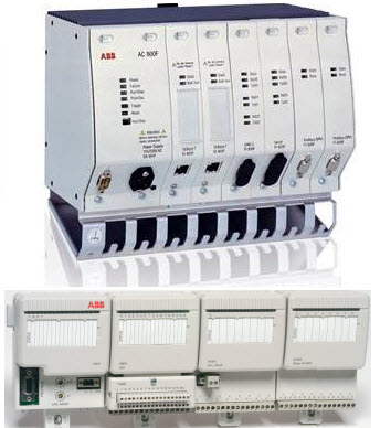
These units acquire the information from various sensors via input module, analyze and process it based on the control logic implemented and sends the output signals via output modules to have control on actuators and relays.
In case of <rel “nofollow” a href=”http://new.abb.com/control-systems/essential-automation/freelance/controller/ac800f” target=”_blank”>ABB DCS, AC800F module (consider, for instance) acts as process station, which is responsible for acquiring and controlling the data from the process. This unit consists of a power supply along with CPU section, Ethernet section, Profibus section and remote communication interface unit for I/Os interfacing as shown in the figure where first module is AC 800F unit and other one is remote I/O (also called as communication interface module).

Communication System

The communication medium plays a major role in the entire distributed control system. It interconnects the engineering station, operating station, process station and smart devices with one another. It carries the information from one station to another. The common communication protocols used in DCS include Ethernet, Profibus, Foundation Field Bus, DeviceNet, Modbus, etc.
It is not mandatory to use one protocol for entire DCS, some levels can use one network whereas some levels use different network. For instance, consider that field devices, distributed I/Os and process station are interconnected with Profibus while the communication among engineering station, HMI and process station carried though Ethernet as shown in the figure below.Communication system in DCS
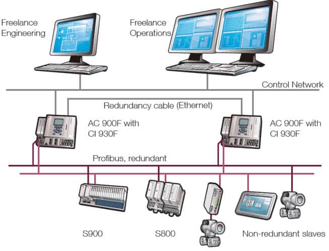
The major advantage of DCS is the redundancy of some or all levels of the control area. Most of the cases critical processes are installed with redundant controllers and redundant communication networks such that problem in main processing line should not affect the monitoring and control functions because of the redundant processing section.

Smart or Intelligent Devices

The intelligent field devices and field bus technology are advanced features of DCS technology that replaces traditional I/O subsystems (I/O modules). These smart devices embed the intelligence required for simple sensing and control techniques into the primary sensing and actuating devices. And hence it replaces the need for a DCS controller to perform routine sensing and control process.
These field devices can be directly connected to field bus so that sourcing of multiple measurements to the next higher level control station is possible via digital transmission line by eliminating extraneous hardware such as local I/O modules and controllers.Smart Field Instrument in DCS

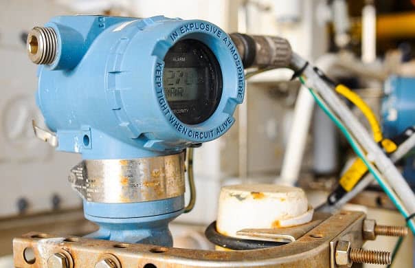
Working & Operation of DCS System

The operation of DCS goes like this; Sensors senses the process information and send it to the local I/O modules, to which actuators are also connected so as to control the process parameters. The information or data from these remote modules is gathered to the process control unit via field bus. If smart field devices are used, the sensed information directly transferred to process control unit via field bus.

DCS working & Operation
The collected information is further processed, analyzed and produces the output results based on the control logic implemented in the controller. The results or control actions are then carried to the actuator devices via field bus. The DCS configuring, commissioning and control logic implementation are carried at the engineering station as mentioned earlier. The operator able to view and send control actions manually at operation stations.

Difference between SCADA and DCS (DCS vs SCADA)

Although both DCS and SCADA are monitoring and control mechanisms in industrial installations, they have different goals. There exist some commonality between DCS and SCADA in terms of hardware and its components, however, there are certain requirements by the end applications that separates a robust and cost-effective DCS from the viable SCADA system. Some of the differences between DCS and SCADA are listed below.Difference between SCADA and DCS
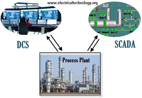
  1. DCS is process oriented, whereas SCADA is data-gathering oriented. DCS emphasizes more on control of the process and it also consists of supervisory control level. And as a part of doing so, it presents the information to the operator. On the other hand, SCADA concentrates more on acquisition process data and presenting it to the operators and control centre.
  2. In DCS, data acquisition and control modules or controllers are usually located within a more confined area and the communication between various distributed control units carried via a local area network. SCADA generally covers larger geographical areas that use different communication systems which are generally less reliable than a local area network.
  3. DCS employs a closed loop control at process control station and at remote terminal units. But in case of SCADA there is no such closed loop control.
  4. DCS is process state driven where it scans the process in regular basis and displays the results to the operator, even on demand. On the other hand, SCADA is event driven where it does not scan the process sequentially, but it waits for an event that cause process parameter to trigger certain actions. Hence, DCS does not keep a database of process parameter values as it always in connection with its data source, whereas SCADA maintains a database to log the parameter values which can be further retrieved for operator display and this makes the SCADA to present the last recorded values if the base station unable to get the new values from a remote location.
  5. In terms of applications, DCS is used for installations within a confined area, like a single plant or factory and for a complex control processes. Some of the application areas of DCS include chemical plants, power generating stations, pharmaceutical manufacturing, oil and gas industries, etc. On the other hand SCADA is used for much larger geographical locations such as water management systems, power transmission and distribution control, transport applications and small manufacturing and process industries.
In spite of these major differences, the modern DCS and SCADA systems come with common standard facilities while dealing process plant automation. However, the choice between DCS and SCADA depends on its client and end application requirement. But if the client choice between these two, by gaining equal requirement from the process, DCS is the economical choice as it help to reduce the cost and offer better control.

DCS Systems from Different Vendors

Some of the available DCS systems include       
  1. Yokogawa- Centum CS 3000 and 1000
  2. ABB- Freelance 800F and 800 xA
  3. Honeywell-TDC 3000
  4. Emerson- Delta V Digital Automation
  5. Siemens- Simatic PCS 7
  6. Allen- Bradley-
Read Also
SCADA Systems for Electrical Distribution
Concept of PID Theory
What is PID Controller & How it Works?
What is Automated Fingerprint Identification System and How it Works?
What is Distributed Control System DCS?
Improving Safety in Machine Control Systems with Limit Switches

IS 3043 / 5039-CODE FOR EARTHING PRACTICE

  •  All medium voltage equipment shall be earthed by two separate and distinct connections with earth In the case of high.
  • And extra high voltage the neutral points shall be earthed by not Less than two separate and distinct connections with earth, each having its own electrode at the generating station or substation and may be earthed at any other point provided ‘no interference is caused by such earthing.

Dec 24, 2017

INSTALLATION AND MAINTENANCE OF POWER AND CONTROL CABLE - IS 1255

INSTALLATION AND MAINTENANCE OF POWER AND CONTROL CABLE FOR UNDERGROUND,AIR,DUCT AND TRAY -    IS 1255 Laying/Erection of Cables


1)    Route Indicator           

  • Power cable route indicators should be provided at an interval not exceeding 200 M and also at turning points of the power cable route wherever practicable”

2)    Electrolytic corrosion:

  • Where the possibility of electrolytic corrosion exists, for example, adjacent to dc traction system, the potential gradient along the pipe-line and the cable sheath should be specified.

3)    Neutral

  • The neutral point is earthed in such a manner that during a line-to-earth fault the highest rms voltage to earth of a sound phase(s) expressed as a percentage of the highest line-to-line voltage, does not exceed 80 percent, irrespective of the fault location,

4)    Earthing

  • The neutral point is not earthed but a device is installed which automatically and instantly cuts out any part of the system which becomes accidentally earthed,
  • In case of ac systems only, the neutral point is earthed through an arc suppression coil with arrangement for isolation within one hour for the non-radial field cables and within 8 hours for radial field cables, of occurrence of the fault provided that the total of such periods in a year does not exceed 125 hours.

5)    Tensile Strength          

  • Maximum Permissible Tensile Strength for Cables: PVC and XLPE insulated armored power cables P = 9 D2 ,P=Pulling Strength(N),D=Outer Diameter of Cable(mm)
  • Maximum Permissible Tensile Strength for Cables: PVC and XLPE insulated unarmored power cables P = 5 D2
  • Maximum Permissible Tensile Strength for Cables: Paper insulated armored power cables P = 5 D3

6)    Cable Pulling  

  1. For Cables Pulled by Pulling Eye :
  2. Expected Pulling Force When Pulling Cables by Winch :
  • If the cables are pulled by gripping the conductor directly with pulling eye, the maximum permissible tensile stress depends on the material of the conductor and on their cross-section as given below: For aluminum conductors 30 N/mm2 and For copper conductors 50 N/mm2″
  • The following values of pulling force are expected = (approximately percentage of cable weight):
  • In trenches without large bends 15-20 percent
  • In trenches with 1 or 2 bends of 90° each 20-40 percent
  • In trenches with 3 bends of 90° each (assuming the use of easy-running support and corner rollers) 50-60 percent
  • In ducts with bends totaling 360° Up to 100 percent”

7)    Laying Direct in Ground          

  • This method involves digging a trench in the ground and laying cable(s) on a bedding of minimum 75 mm riddled soil or sand at the bottom of the trench, and covering it with additional riddled soil or sand of minimum 75 mm and protecting it by means of tiles, bricks
  • Depth — The desired minimum depth of laying from ground surface to the top of cable is as follows:
  • High voltage cables, 3.3 kV to 11 kV rating =0.9 m
  • High voltage cables, 22 kV, 33 kV rating= 1.05 m
  • Low voltage and control cables = 0.75 m
  • Cables at road crossings = 1.00 m

8)    Cables at railway

  • Cables at railway level crossings (measured from bottom of sleepers to the top of pipe)=1.00m”

9)    Cable Clearance          

  • Clearances — The desired minimum clearances are
  • Power cable to power cable = Clearance not necessary; however, larger the clearance, better would be current carrying capacity.
  • Power cable to control cables = 0.2 m
  • Power cable to communication cable = 0.3 m
  • Power cable to gas/water main = 0.3m
  •  Inductive influence on sensitive control cable on account of nearby power cables should be checked”
  • The power cable should not be laid above the telecommunication cable, to avoid danger to life of the person, digging to attend to the fault in the Telecommunication cable.
10) Crossing         
  • Cables Laid Across Roads, Railway Tracks and Water Pipe Lines:
  • Steel, cast iron, plastics, cement or earthenware ducts, or cable ducting blocks should be used where cables cross roads and railway tracks.
  • Spare ducts for future extensions should be provided.
  • Spare duct runs should be sealed off.
  • Buried ducts or ducting blocks should  project into footpath or up to the edge of road,
  • where there is no footpath, to permit smooth entry of cable without undue bending

11) Diameter of Pipe         

  • The diameter of the cable conduit or pipe or duct should be at least 1.5 times the outer diameter of cable.
  • The ducts/pipes should be mechanically strong to withstand forces due to heavy traffic when they are laid across road/railway tracks.

12) Bending Radius          

  • The bending radius of steel or plastics ducts should not be less than 1.5 m.

13) Over Bridge     

  • On bridges, the cables are generally supported on steel cable hooks or clamped on steel supports at regular intervals.
  • While designing a cable layout on a bridge; expansion of bridge due to changes in atmospheric temperature should be taken into account.
  • On most of the rail-cum-road bridges, the cables are subjected to vibrations.
  • For such conditions, round wire armored and lead alloy ‘B’ sheathed cables are preferred.
  • Cables can be laid on bridges duly suspended from catenary wire at regular intervals

14) Railway Crossing        

  • When the cables are laid under railway tracks the cables should be laid in reinforced spun concrete or cast iron or steel pipes
  • at such depths as may be specified by the railway authorities but not less than 1 m measured from the bottom of sleepers to the top of the pipe.
  • On long run ducts, it is desirable to apply lubrication to the lead or serving/outer sheath as it enters the duct.
  • Petroleum jelly or graphite powder or a combination of both is effective for this purpose and through lubrication will reduce the pulling tension by about 40 percent.

15) Laying on Racks in Air

  • The vertical distance between the two racks should be minimum 0.3 m and the clearance between the first cable and the wall (if racks
  • are mounted on wall) should be 25 mm.
  • The width of the rack should not exceed 0.75 m in order to facilitate installation of cables.
  • Ungalvanized steel work of cable racking/trays should be painted with a coat of primer and thereafter finished with suitable anti-corrosive paint.
  • Only single-core cables laid on horizontal racks need be clamped at suitable intervals. Multi-core cables need not be clamped. The distance between the vertical clamps should not be more than 2 m.
  • Laying Cables on Racks Inside a Tunnel: Horizontal distance between Two cable is min Diameter of Cable and vertical distance between two cable row is 30cm.In cable tunnel, the head room should not be less than 2 m and width sufficient to leave a free passage of at least 600 to 800 mm either from one side or in the middle.
  • With temperatures below 3°C, the cables should be warmed before the laying out, since otherwise the bending would damage the insulation and protective coverings of cables. The cable laying must be carried out swiftly, so that the cable does not cool down too much
  • Identification strips/tags of metal or plastics should be attached to the cables, particularly if several are laid in parallel, 8 to 10 m apart. Identification tags should also be attached at every entry point into the buildings and at the cable end termination
  • The spacing between three cables laid in one plane should be not less than the cable diameter.
  • When the cable run is several kilometers long, the cables should be transposed at one-third and at two-thirds of the total lengths.

16) Trefoil arrangement in ducts   

  • If several single-core cables are laid per phase, these should be arranged as follows to ensure balanced current distribution
  • in Horizontal direction : R-Y-B-Distance-B-Y-R, (Distance=2 X Diameter of  Cable) , vertical distance shall be 6 X Diameter of Cable

17) Insulation Color          

  • For reduced neutral conductors, the insulation color shall be black.
  • For cables having more than 5 cores, the core identification may be done by numbers. In that case, the insulation of cores shall be of the same color and numbered sequentially, starting with number 1 for the inner layer. The numbers shall be printed in Hindu-Arabic numerals on the outer surface of the cores. All
  • The numbers shall be of the same color which shall contrast with the color of the insulation. The numerals shall be legible.”
  • When the number is a single numeral, a dash shall be placed underneath it. If the number consists of two numerals, these shall be disposed one below the other and a dash placed below the lower numeral. The spacing between consecutive numbers shall not exceed 50 mm.

18) Type of Armoring:

  • Where the calculated diameter below armoring does not exceed 13 mm, the armor shall consist of galvanized round steel wires. Where the calculated
  • Diameter below armoring is greater than 13 mm, the armor shall consist of either galvanized round steel wires or galvanized steel strips.

19) Identification/Marking 

  • Type of Cable Legend:
  • Improved fire performance or Category C1  FR
  • Cables in constrained areas, Does not propagate fire even when installed in groups in vertical ducts),
  • Improved fire performance for Category C2 FR—LSH (Cables in constrained areas with limited human activity and/or presence of  sophisticated systems)
  • Aluminum conductor= A,
  • PVC insulation=Y, Steel round wire armor= W,
  • Steel strip armor= F,
  • Steel double round wire armor= WW,
  • Steel double strip armor =FF,
  • PVC outer sheath= Y

20) Cable Route Indicator (Up to 33KV)

  • Route indicators — Power cable route indicators should be provided at an interval not exceeding 200 M and also at turning points
    of the power cable route wherever practicable.

21) Cable Corrosion  (Up to 33KV)

  • Electrolytic corrosion — Where the possibility of electrolytic corrosion exists, for example, adjacent to dc traction system, the potential gradient along the pipe-line and the cable sheath should be specified.

22) Neutral (Up to 33KV)

  • The neutral point is earthed in such a manner that during a line-to-earth fault the highest rms voltage to earth of a sound phase(s) expressed as a percentage of the highest line-to-line voltage, does not exceed 80 percent, irrespective of the fault location,

23) Earthing   (Up to 33KV)


  • The neutral point is not earthed but a device is installed which automatically and instantly cuts out any part of the system which becomes accidentally earthed,
  • In case of ac systems only, the neutral point is earthed through an arc suppression coil with arrangement for isolation within one hour for the non-radial field cables and within 8 hours for radial field cables, of occurrence of the fault provided that the total of such periods in a year does not exceed 125 hours.

24) Cable Tensile Strength (Up to 33KV)

  • Maximum Permissible Tensile Strength for Cables: PVC and XLPE insulated armored power cables P = 9 D2 ,P=Pulling Strength(N),D=Outer Dia of Cable(mm)
  • Maximum Permissible Tensile Strength for Cables: PVC and XLPE insulated unarmored power cables P = 5 D2
  • Maximum Permissible Tensile Strength for Cables: Paper insulated armored power cables P = 5 D3

25) Cable Pulling   (Up to 33KV)

  • For Cables Pulled by Pulling Eye — If the cables are pulled by gripping the conductor directly with pulling eye, the maximum permissible tensile stress depends on the material of the conductor and on their cross-section as given below: For aluminum conductors 30 N/mm2 and
    For copper conductors 50 N/mm2
  • Expected Pulling Force When Pulling Cables by Winch — The following values of pulling force are expected:
  • P = (approximately percentage of cable weight): In trenches without large bends 15-20 %
  • In trenches with 1 or 2 bends of 90° each 20-40 %
  • In trenches with 3 bends of 90° each (assuming the use of easy-running support and corner rollers) 50-60 %
  • In ducts with bends totaling 360° Up to 100 %

26) Cable Laying Direct in Ground  (Up to 33KV)

  • This method involves digging a trench in the ground and laying cable(s) on a bedding of minimum 75 mm riddled soil or sand at the bottom of the trench, and covering it with additional riddled soil or sand of minimum 75 mm and protecting it by means of tiles, bricks
  • Depth — The desired minimum depth of laying from ground surface to the top of cable is as follows: 
  • High voltage cables, 3.3 kV to 11 kV rating =0.9 m
  • High voltage cables, 22 kV, 33 kV rating= 1.05 m
  • Low voltage and control cables = 0.75 m
  • Cables at road crossings = 1.00 m
  • Cables at railway level crossings (measured from bottom of sleepers to the top of pipe)=1.00m

27) Cable Clearance (Up to 33KV)

  • Clearances: The desired minimum clearances are as follow:
  • Power cable to power cable = Clearance not necessary; however, larger the clearance, better would be current carrying capacity
  • Power cable to control cables = 0.2 m
  • Power cable to communication cable = 0.3 m
  • Power cable to gas/water main =0.3m
  • Inductive influence on sensitive control cable on account of nearby power cables should be checked
  • The power cable should not be laid above the telecommunication cable, to avoid danger to life of the person, digging to attend to the fault in the Telecommunication cable.

28) Crossing (Up to 33KV)

  • Cables Laid Across Roads, Railway Tracks and Water Pipe Lines: Steel, cast iron, plastics, cement or earthenware ducts, or cable ducting blocks should be used where cables cross roads and railway tracks. Spare ducts for future extensions should be provided. Spare duct runs should be sealed off. Buried ducts or ducting blocks should  project into footpath or up to the edge of road, where there is no footpath, to permit smooth entry of cable without undue bending

29) Diameter of Pipe  (Up to 33KV)

  • The diameter of the cable conduit or pipe or duct should be at least 1.5 times the outer diameter of cable. The ducts/pipes should be mechanically strong to withstand forces due to heavy traffic when they are laid across road/railway tracks.

30) Bending Radius (Up to 33KV)

  • The bending radius of steel or plastics ducts should not be less than 1.5 m.

31) Cable on Over Bridge (Up to 33KV)

  • Cable Over Bridges — On bridges, the cables are generally supported on steel cable hooks or clamped on steel supports at regular intervals. While designing a cable layout on a bridge; expansion of bridge due to changes in atmospheric temperature should be taken into account. On most of the rail-cum-road bridges, the cables are subjected to vibrations. For such conditions, round wire armored and lead alloy ‘B’ sheathed cables are preferred. Cables can be laid on bridges duly suspended from catenary wire at regular intervals

32) Cable on Railway Crossing (Up to 33KV)

  • Cables Below Railway Crossing — When the cables are laid under railway tracks the cables should be laid in reinforced spun concrete or cast iron or steel pipes at such depths as may be specified by the railway authorities but not less than 1 m measured from the bottom of sleepers to the top of the pipe

33) Cable on Duct (Up to 33KV)

  • On long run ducts, it is desirable to apply lubrication to the lead or serving/outer sheath as it enters the duct. Petroleum jelly or graphite powder or a combination of both is effective for this purpose and through lubrication will reduce the pulling tension by about 40 percent.

34) Laying on Racks in Air (Up to 33KV)

  • Lying on Racks in Air-The vertical distance between the two racks should be minimum 0.3 m and the clearance between the first cable and the wall (if racks are mounted on wall) should be 25 mm. The width of the rack should not exceed 0.75 m in order to facilitate installation of cables.
  • Un galvanized steel work of cable racking/trays should be painted with a coat of primer and thereafter finished with suitable anti-corrosive paint.
  • Only single-core cables laid on horizontal racks need be clamped at suitable intervals. Multi-core cables need not be clamped. The distance between the vertical clamps should not be more than 2 m

35) Laying Cables on Racks Inside a Tunnel (Up to 33KV)

  • Laying Cables on Racks Inside a Tunnel: Horizontal distance between Two cable is min Diameter of Cable and vertical distance between two cable row is 30cm.In cable tunnel, the head room should not be less than 2 m and width sufficient to leave a free passage of at least 600 to 800 mm either from one side or in the middle.
  • With temperatures below 3°C, the cables should be warmed before the laying out, since otherwise the bending would damage the insulation and protective coverings of cables. The cable laying must be carried out swiftly, so that the cable does not cool down too much
  • Identification strips/tags of metal or plastics should be attached to the cables, particularly if several are laid in parallel, 8 to 10 m apart. Identification tags should also be attached at every entry point into the buildings and at the cable end termination
  • The spacing between three cables laid in one plane should be not less than the cable diameter.
  • When the cable run is several kilometers long, the cables should be transposed at one-third and at two-thirds of the total lengths.

36) Trefoil arrangement in ducts (Up to 33KV)

  • If several single-core cables are laid per phase, these should be arranged as follows to ensure balanced current distribution in Horizontal direction : R-Y-B-Distance-B-Y-R, (Distance=2 X Diameter of  Cable) , vertical distance shall be 6 X Diameter of Cable.

Search This Blog