Showing posts with label AC/DC. Show all posts

Mar 11, 2018

Single-phase power systems

Single-phase

                            
Depicted above is a very simple AC circuit. If the load resistor's power dissipation were substantial, we might call this a "power circuit" or "power system" instead of regarding it as just a regular circuit. The distinction between a "power circuit" and a "regular circuit" may seem arbitrary, but the practical concerns are definitely not.
One such concern is the size and cost of wiring necessary to deliver power from the AC source to the load. Normally, we do not give much thought to this type of concern if we're merely analyzing a circuit for the sake of learning about the laws of electricity. However, in the real world it can be a major concern. If we give the source in the above circuit a voltage value and also give power dissipation values to the two load resistors, we can determine the wiring needs for this particular circuit:


83.33 amps for each load resistor adds up to 166.66 amps total circuit current. This is no small amount of current, and would necessitate copper wire conductors of at least 1/0 gage. Such wire is well over 1/4 inch in diameter, weighing over 300 pounds per thousand feet. Bear in mind that copper is not cheap either! It would be in our best interest to find ways to minimize such costs if we were designing a power system with long conductor lengths.
One way to do this would be to increase the voltage of the power source and use loads built to dissipate 10 kW each at this higher voltage. The loads, of course, would have to have greater resistance values to dissipate the same power as before (10 kW each) at a greater voltage than before. The advantage would be less current required, permitting the use of smaller, lighter, and cheaper wire:


Now our total circuit current is 83.33 amps, half of what it was before. We can now use number 4 gage wire, which weighs less than half of what 1/0 gage wire does per unit length. This is a considerable reduction in system cost with no degradation in performance. This is why power distribution system designers elect to transmit electric power using very high voltages (many thousands of volts): to capitalize on the savings realized by the use of smaller, lighter, cheaper wire.
However, this solution is not without disadvantages. Another practical concern with power circuits is the danger of electric shock from high voltages. Again, this is not usually the sort of thing we concentrate on while learning about the laws of electricity, but it is a very valid concern in the real world, especially when large amounts of power are being dealt with. The gain in efficiency realized by stepping up the circuit voltage presents us with increased danger of electric shock. Power distribution companies tackle this problem by stringing their power lines along high poles or towers, and insulating the lines from the supporting structures with large, porcelain insulators.
At the point of use (the electric power customer), there is still the issue of what voltage to use for powering loads. High voltage gives greater system efficiency by means of reduced conductor current, but it might not always be practical to keep power wiring out of reach at the point of use the way it can be elevated out of reach in distribution systems. This tradeoff between efficiency and danger is one that European power system designers have decided to risk, all their households and appliances operating at a nominal voltage of 240 volts instead of 120 volts as it is in North America. That is why tourists from America visiting Europe must carry small step-down transformers for their portable appliances, to step the 240 VAC (volts AC) power down to a more suitable 120 VAC.
Is there any way to realize the advantages of both increased efficiency and reduced safety hazard at the same time? One solution would be to install step-down transformers at the end-point of power use, just as the American tourist must do while in Europe. However, this would be expensive and inconvenient for anything but very small loads (where the transformers can be built cheaply) or very large loads (where the expense of thick copper wires would exceed the expense of a transformer).
An alternative solution would be to use a higher voltage supply to provide power to two lower voltage loads in series. This approach combines the efficiency of a high-voltage system with the safety of a low-voltage system:
Voltage "polarity," AC Polarity, AC Polarity, AC
Notice the polarity markings (+ and -) for each voltage shown, as well as the unidirectional arrows for current. For the most part, I've avoided labeling "polarities" in the AC circuits we've been analyzing, even though the notation is valid to provide a frame of reference for phase. In later sections of this chapter, phase relationships will become very important, so I'm introducing this notation early on in the chapter for your familiarity.
The current through each load is the same as it was in the simple 120 volt circuit, but the currents are not additive because the loads are in series rather than parallel. The voltage across each load is only 120 volts, not 240, so the safety factor is better. Mind you, we still have a full 240 volts across the power system wires, but each load is operating at a reduced voltage. If anyone is going to get shocked, the odds are that it will be from coming into contact with the conductors of a particular load rather than from contact across the main wires of a power system.
There's only one disadvantage to this design: the consequences of one load failing open, or being turned off (assuming each load has a series on/off switch to interrupt current) are not good. Being a series circuit, if either load were to open, current would stop in the other load as well. For this reason, we need to modify the design a bit:
Hot conductor Neutral conductor


Split-phase
Instead of a single 240 volt power supply, we use two 120 volt supplies (in phase with each other!) in series to produce 240 volts, then run a third wire to the connection point between the loads to handle the eventuality of one load opening. This is called a split-phase power system. Three smaller wires are still cheaper than the two wires needed with the simple parallel design, so we're still ahead on efficiency. The astute observer will note that the neutral wire only has to carry the difference of current between the two loads back to the source. In the above case, with perfectly "balanced" loads consuming equal amounts of power, the neutral wire carries zero current.
Notice how the neutral wire is connected to earth ground at the power supply end. This is a common feature in power systems containing "neutral" wires, since grounding the neutral wire ensures the least possible voltage at any given time between any "hot" wire and earth ground.
An essential component to a split-phase power system is the dual AC voltage source. Fortunately, designing and building one is not difficult. Since most AC systems receive their power from a step-down transformer anyway (stepping voltage down from high distribution levels to a user-level voltage like 120 or 240), that transformer can be built with a center-tapped secondary winding:
If the AC power comes directly from a generator (alternator), the coils can be similarly center-tapped for the same effect. The extra expense to include a center-tap connection in a transformer or alternator winding is minimal.
Boosting, AC voltage sources Bucking, AC voltage sources
Here is where the (+) and (-) polarity markings really become important. This notation is often used to reference the phasings of multiple AC voltage sources, so it is clear whether they are aiding ("boosting") each other or opposing ("bucking") each other. If not for these polarity markings, phase relations between multiple AC sources might be very confusing. Note that the split-phase sources in the schematic (each one 120 volts0o), with polarity marks (+) to (-) just like series-aiding batteries can alternatively be represented as such:
To mathematically calculate voltage between "hot" wires, we must subtract voltages, because their polarity marks show them to be opposed to each other:
If we mark the two sources' common connection point (the neutral wire) with the same polarity mark (-), we must express their relative phase shifts as being 180o apart. Otherwise, we'd be denoting two voltage sources in direct opposition with each other, which would give 0 volts between the two "hot" conductors. Why am I taking the time to elaborate on polarity marks and phase angles? It will make more sense in the next section!
Single-phase
Power systems in American households and light industry are most often of the split-phase variety, providing so-called 120/240 VAC power. The term "split-phase" merely refers to the split-voltage supply in such a system. In a more general sense, this kind of AC power supply is called single phase because both voltage waveforms are in phase, or in step, with each other.
The term "single phase" is a counterpoint to another kind of power system called "polyphase" which we are about to investigate in detail. Apologies for the long introduction leading up to the title-topic of this chapter. The advantages of polyphase power systems are more obvious if one first has a good understanding of single phase systems.

Review
  • Single phase power systems are defined by having an AC source with only one voltage waveform.
  • A split-phase power system is one with multiple (in-phase) AC voltage sources connected in series, delivering power to loads at more than one voltage, with more than two wires. They are used primarily to achieve balance between system efficiency (low conductor currents) and safety (low load voltages).
  • Split-phase AC sources can be easily created by center-tapping the coil windings of transformers or alternators.

Mar 2, 2018

Three-phase power systems

Three-phase/Poly phase/Three-wire DC system

Split-phase power systems achieve their high conductor efficiency and low safety risk by splitting up the total voltage into lesser parts and powering multiple loads at those lesser voltages, while drawing currents at levels typical of a full-voltage system. This technique, by the way, works just as well for DC power systems as it does for single-phase AC systems. Such systems are usually referred to as three-wire systems rather than split-phasebecause "phase" is a concept restricted to AC.
But we know from our experience with vectors and complex numbers that AC voltages don't always add up as we think they would if they are out of phase with each other. This principle, applied to power systems, can be put to use to make power systems with even greater conductor efficiencies and lower shock hazard than with split-phase.
Suppose that we had two sources of AC voltage connected in series just like the split-phase system we saw before, except that each voltage source was 120o out of phase with the other:
Since each voltage source is 120 volts, and each load resistor is connected directly in parallel with its respective source, the voltage across each load must be 120 volts as well. Given load currents of 83.33 amps, each load must still be dissipating 10 kilowatts of power. However, voltage between the two "hot" wires is not 240 volts (1200° - 120180o) because the phase difference between the two sources is not 180o. Instead, the voltage is:
Nominally, we say that the voltage between "hot" conductors is 208 volts (rounding up), and thus the power system voltage is designated as 120/208.
If we calculate the current through the "neutral" conductor, we find that it is not zero, even with balanced load resistances. Kirchhoff's Current Law tells us that the currents entering and exiting the node between the two loads must be zero:

So, we find that the "neutral" wire is carrying a full 83.33 amps, just like each "hot" wire.
Note that we are still conveying 20 kW of total power to the two loads, with each load's "hot" wire carrying 83.33 amps as before. With the same amount of current through each "hot" wire, we must use the same gage copper conductors, so we haven't reduced system cost over the split-phase 120/240 system. However, we have realized a gain in safety, because the overall voltage between the two "hot" conductors is 32 volts lower than it was in the split-phase system (208 volts instead of 240 volts).
The fact that the neutral wire is carrying 83.33 amps of current raises an interesting possibility: since it's carrying current anyway, why not use that third wire as another "hot" conductor, powering another load resistor with a third 120 volt source having a phase angle of 240o? That way, we could transmit more power (another 10 kW) without having to add any more conductors. Let's see how this might look:

Superposition Theorem Theorem, Superposition
A full mathematical analysis of all the voltages and currents in this circuit would necessitate the use of a network theorem, the easiest being the Superposition Theorem. I'll spare you the long, drawn-out calculations because you should be able to intuitively understand that the three voltage sources at three different phase angles will deliver 120 volts each to a balanced triad of load resistors. For proof of this, we can use SPICE to do the math for us:

120/208 polyphase power system
v1 1 0 ac 120 0 sin
v2 2 0 ac 120 120 sin
v3 3 0 ac 120 240 sin
r1 1 4 1.44
r2 2 4 1.44
r3 3 4 1.44
.ac lin 1 60 60
.print ac v(1,4) v(2,4) v(3,4)
.print ac v(1,2) v(2,3) v(3,1)
.print ac i(v1) i(v2) i(v3)
.end


VOLTAGE ACROSS EACH LOAD
freq        v(1,4)      v(2,4)      v(3,4)
6.000E+01   1.200E+02   1.200E+02   1.200E+02

VOLTAGE BETWEEN "HOT" CONDUCTORS
freq        v(1,2)      v(2,3)      v(3,1)
6.000E+01   2.078E+02   2.078E+02   2.078E+02

CURRENT THROUGH EACH VOLTAGE SOURCE
freq        i(v1)       i(v2)       i(v3)
6.000E+01   8.333E+01   8.333E+01   8.333E+01
Sure enough, we get 120 volts across each load resistor, with (approximately) 208 volts between any two "hot" conductors and conductor currents equal to 83.33 amps. At that current and voltage, each load will be dissipating 10 kW of power. Notice that this circuit has no "neutral" conductor to ensure stable voltage to all loads if one should open. What we have here is a situation similar to our split-phase power circuit with no "neutral" conductor: if one load should happen to fail open, the voltage drops across the remaining load(s) will change. To ensure load voltage stability in the even of another load opening, we need a neutral wire to connect the source node and load node together:
So long as the loads remain balanced (equal resistance, equal currents), the neutral wire will not have to carry any current at all. It is there just in case one or more load resistors should fail open (or be shut off through a disconnecting switch).
Polyphase Three-phase
This circuit we've been analyzing with three voltage sources is called a polyphase circuit. The prefix "poly" simply means "more than one," as in "polytheism" (belief in more than one deity), polygon" (a geometrical shape made of multiple line segments: for example, pentagon and hexagon), and "polyatomic" (a substance composed of multiple types of atoms). Since the voltage sources are all at different phase angles (in this case, three different phase angles), this is a "polyphase" circuit. More specifically, it is a three-phase circuit, the kind used predominantly in large power distribution systems.
Let's survey the advantages of a three-phase power system over a single-phase system of equivalent load voltage and power capacity. A single-phase system with three loads connected directly in parallel would have a very high total current (83.33 times 3, or 250 amps:
This would necessitate 3/0 gage copper wire (very large!), at about 510 pounds per thousand feet, and with a considerable price tag attached. If the distance from source to load was 1000 feet, we would need over a half-ton of copper wire to do the job. On the other hand, we could build a split-phase system with two 15 kW, 120 volt loads:
Our current is half of what it was with the simple parallel circuit, which is a great improvement. We could get away with using number 2 gage copper wire at a total mass of about 600 pounds, figuring about 200 pounds per thousand feet with three runs of 1000 feet each between source and loads. However, we also have to consider the increased safety hazard of having 240 volts present in the system, even though each load only receives 120 volts. Overall, there is greater potential for dangerous electric shock to occur.
When we contrast these two examples against our three-phase system, the advantages are quite clear. First, the conductor currents are quite a bit less (83.33 amps versus 125 or 250 amps), permitting the use of much thinner and lighter wire. We can use number 4 gage wire at about 125 pounds per thousand feet, which will total 500 pounds (four runs of 1000 feet each) for our example circuit. This represents a significant cost savings over the split-phase system, with the additional benefit that the maximum voltage in the system is lower (208 versus 240).
One question remains to be answered: how in the world do we get three AC voltage sources whose phase angles are exactly 120o apart? Obviously we can't center-tap a transformer or alternator winding like we did in the split-phase system, since that can only give us voltage waveforms that are either in phase or 180o out of phase. Perhaps we could figure out some way to use capacitors and inductors to create phase shifts of 120o, but then those phase shifts would depend on the phase angles of our load impedances as well (substituting a capacitive or inductive load for a resistive load would change everything!).
Alternator Generator
The best way to get the phase shifts we're looking for is to generate it at the source: construct the AC generator (alternator) providing the power in such a way that the rotating magnetic field passes by three sets of wire windings, each set spaced 120o apart around the circumference of the machine:
Pole, alternator
Together, the six "pole" windings of a three-phase alternator are connected to comprise three winding pairs, each pair producing AC voltage with a phase angle 120o shifted from either of the other two winding pairs. The interconnections between pairs of windings (as shown for the single-phase alternator: the jumper wire between windings 1a and 1b) have been omitted from the three-phase alternator drawing for simplicity.
Y configuration Star configuration
In our example circuit, we showed the three voltage sources connected together in a "Y" configuration (sometimes called the "star" configuration), with one lead of each source tied to a common point (the node where we attached the "neutral" conductor). The common way to depict this connection scheme is to draw the windings in the shape of a "Y" like this:
The "Y" configuration is not the only option open to us, but it is probably the easiest to understand at first. More to come on this subject later in the chapter.

Summery 
A single-phase power system is one where there is only one AC voltage source (one source voltage waveform).
A split-phase power system is one where there are two voltage sources, 180o phase-shifted from each other, powering a two series-connected loads. The advantage of this is the ability to have lower conductor currents while maintaining low load voltages for safety reasons.

A polyphase power system uses multiple voltage sources at different phase angles from each other (many "phases" of voltage waveforms at work). A polyphase power system can deliver more power at less voltage with smaller-gage conductors than single- or split-phase systems. 

The phase-shifted voltage sources necessary for a polyphase power system are created in alternators with multiple sets of wire windings. These winding sets are spaced around the circumference of the rotor's rotation at the desired angle(s).

Feb 11, 2018

Concept of Inrush current

Inrush current

When a transformer is initially connected to a source of AC voltage, there may be a substantial surge of current through the primary winding called inrush current. This is analogous to the inrush current exhibited by an electric motor that is started up by sudden connection to a power source, although transformer inrush is caused by a different phenomenon.
We know that the rate of change of instantaneous flux in a transformer core is proportional to the instantaneous voltage drop across the primary winding. Or, as stated before, the voltage waveform is the derivative of the flux waveform, and the flux waveform is the integral of the voltage waveform. In a continuously-operating transformer, these two waveforms are phase-shifted by 90o. Since flux (Φ) is proportional to the magnetomotive force (mmf) in the core, and the mmf is proportional to winding current, the current waveform will be in-phase with the flux waveform, and both will be lagging the voltage waveform by 90o:

Feb 10, 2018

Power in resistive and reactive AC circuits

Resistive and reactive AC circuits

Consider a circuit for a single-phase AC power system, where a 120 volt, 60 Hz AC voltage source is delivering power to a resistive load:

Feb 7, 2018

Basic Concepts Of Electricity

Static Electricity

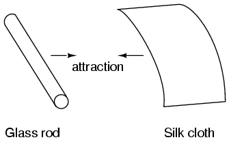
It was discovered centuries ago that certain types of materials would mysteriously attract one another after being rubbed together. For example: after rubbing a piece of silk against a piece of glass, the silk and glass would tend to stick together. Indeed, there was an attractive force that could be demonstrated even when the two materials were separated:

Working principal of Volt and Current in Measuring circuit

 Voltmeters and Ammeters

AC electromechanical meter movements come in two basic arrangements: those based on DC movement designs, and those engineered specifically for AC use. Permanent-magnet moving coil (PMMC) meter movements will not work correctly if directly connected to alternating current, because the direction of needle movement will change with each half-cycle of the AC. Permanent-magnet meter movements, like permanent-magnet motors, are devices whose motion depends on the polarity of the applied voltage (or, you can think of it in terms of the direction of the current).

Feb 2, 2018

Concept of AC Bridge Circuits

AC Bridge Circuits


As we saw with DC measurement circuits, the circuit configuration known as a bridge can be a very useful way to measure unknown values of resistance. This is true with AC as well, and we can apply the very same principle to the accurate measurement of unknown impedance. To review, the bridge circuit works as a pair of two-component voltage dividers connected across the same source voltage, with a null-detector meter movement connected between them to indicate a condition of “balance” at zero volts: (Figure below)

A balanced bridge shows a “null”, or minimum reading, on the indicator.

Jan 28, 2018

Power measurement of AC & DC circuits

Power measurement

Power measurement in AC circuits can be quite a bit more complex than with DC circuits for the simple reason that phase shift makes complicates the matter beyond multiplying voltage by current figures obtained with meters. What is needed is an instrument able to determine the product (multiplication) of instantaneous voltage and current. Fortunately, the common electrodynamometer movement with its stationary and moving coil does a fine job of this.
Three phase power measurement can be accomplished using two dynamometer movements with a common shaft linking the two moving coils together so that a single pointer registers power on a meter movement scale. This, obviously, makes for a rather expensive and complex movement mechanism, but it is a workable solution. An ingenious method of deriving an electronic power meter (one that generates an electric signal representing power in the system rather than merely move a pointer) is based on the Hall Effect. The Hall Effect is an unusual effect first noticed by E. H. Hall in 1879, whereby a voltage is generated along the width of a current-carrying conductor exposed to a perpendicular

magnetic field
The voltage generated across the width of the flat, rectangular conductor is directly proportional to both the magnitude of the current through it and the strength of the magnetic field. Mathematically, it is a product (multiplication) of these two variables. The amount of "Hall Voltage" produced for any given set of conditions also depends on the type of material used for the flat, rectangular conductor. It has been found that specially prepared "semiconductor" materials produce a greater Hall voltage than do metals, and so modern Hall Effect devices are made of these. It makes sense then that if we were to build a device using a Hall-effect sensor where the current through the conductor was pushed by AC voltage from an external circuit and the magnetic field was set up by a pair or wire coils energized by the current of the AC power circuit, the Hall voltage would be in direct proportion to the multiple of circuit current and voltage. Having no mass to move (unlike an electromechanical movement), this device is able to provide instantaneous power measurement:

Not only will the output voltage of the Hall Effect device be the representation of instantaneous power at any point in time, but it will also be a DC signal! This is because the Hall voltage polarity is dependent upon both the polarity of the magnetic field and the direction of current through the conductor. If both current direction and magnetic field polarity reverses -- as it would ever half-cycle of the AC power -- the output voltage polarity will stay the same. If voltage and current in the power circuit are 90o out of phase (a power factor of zero, meaning no real power delivered to the load), the alternate peaks of Hall device current and magnetic field will never coincide with each other: when one is at its peak, the other will be zero. At those points in time, the Hall output voltage will likewise be zero, being the product (multiplication) of current and magnetic field strength. Between those points in time, the Hall output voltage will fluctuate equally between positive and negative, generating a signal corresponding to the instantaneous absorption and release of power through the reactive load. The net DC output voltage will be zero, indicating zero true power in the circuit. Any phase shift between voltage and current in the power circuit less than 90o will result in a Hall output voltage that oscillates between positive and negative, but spends more time positive than negative. Consequently there will be a net DC output voltage. Conditioned through a low-pass filter circuit, this net DC voltage can be separated from the AC mixed with it, the final output signal registered on a sensitive DC meter movement. Often it is useful to have a meter to totalize power usage over a period of time rather than instantaneously. The output of such a meter can be set in units of Joules, or total energy consumed, since power is a measure of work being done per unit time. Or, more commonly, the output of the meter can be set in units of Watt-Hours. Mechanical means for measuring Watt-Hours are usually cantered around the concept of the motor: build an AC motor that spins at a rate of speed proportional to the instantaneous power in a circuit, then have that motor turn an "odometer" style counting mechanism to keep a running total of energy consumed. The "motor" used in these meters has a rotor made of a thin aluminium disk, with the rotating magnetic field established by sets of coils energized by line voltage and load current so that the rotational speed of the disk is dependent on both voltage and current.
Read Also
Transformer Winding configurations
Basic concept and Calculating of Power Factor
Step-up and step-down transformers
Circuit Schematic Symbols
what is AC commutator motors?
Concept of Brush less DC motor
Concept of Reluctance of motor
Single-phase induction motors concept
Types of specialized motors
Construction & operation of Poly phase motor
What is self synchronous motors?
what is AC commutator motors?
Step-up and step-down transformers
Circuit Schematic Symbols

Jan 16, 2018

AC Capacitor & Resistor Circuits

AC Capacitor/Resistor Circuits

1. AC Capacitor  Circuits

Capacitors do not behave the same as resistors. Whereas resistors allow a flow of electrons through them directly proportional to the voltage drop, capacitors oppose changes in voltage by drawing or supplying current as they charge or discharge to the new voltage level. The flow of electrons "through" a capacitor is directly proportional to the rate of change of voltage across the capacitor. This opposition to voltage change is another form of reactance, but one that is precisely opposite to the kind exhibited by inductors.

How to Measurements of AC magnitude?

Measurements of AC magnitude

So far we know that AC voltage alternates in polarity and AC current alternates in direction. We also know that AC can alternate in a variety of different ways, and by tracing the alternation over time we can plot it as a "waveform." We can measure the rate of alternation by measuring the time it takes for a wave to evolve before it repeats itself (the "period"), and express this as cycles per unit time, or "frequency." In music, frequency is the same as pitch, which is the essential property distinguishing one note from another.

What is alternating current (AC)?

Alternating current

Most students of electricity begin their study with what is known as direct current (DC), which is electricity flowing in a constant direction, and/or possessing a voltage with constant polarity. DC is the kind of electricity made by a battery (with definite positive and negative terminals), or the kind of charge generated by rubbing certain types of materials against each other.

Jan 15, 2018

Concept of Voltage & Current signal systems

1. Current signal systems


Signal, current Current signal Current source Source, current
It is possible through the use of electronic amplifiers to design a circuit outputting a constant amount of current rather than a constant amount of voltage. This collection of components is collectively known as a current source, and its symbol looks like this:

How voltage, current, and resistance related

How voltage,current and resistance 

An electric circuit is formed when a conductive path is created to allow free electrons to continuously move. This continuous movement of free electrons through the conductors of a circuit is called a current, and it is often referred to in terms of "flow," just like the flow of a liquid through a hollow pipe.

Basic Concept of Electricity for DC circuit-Static electricity Part A

Static electricity

It was discovered centuries ago that certain types of materials would mysteriously attract one another after being rubbed together. For example: after rubbing a piece of silk against a piece of glass, the silk and glass would tend to stick together. Indeed, there was an attractive force that could be demonstrated even when the two materials were separated:

Search This Blog