
Star Point grounding
Part-BPlease read Part-A Post for better understanding .

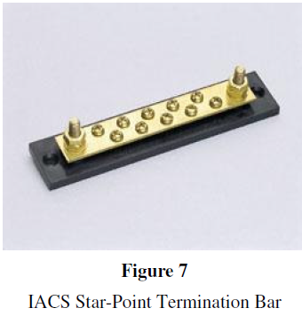
For IACS control panel star-point terminal blocks, a corrosion resistant, stainless steel or nickel plated busbar is the heart of a star-point grounding system as shown in Figure 7.
How Not to Ground!
Do not ground various elements of the IACS i.e., shields from field transmitters and the DCS/PLC power supply ground, to different grounds. Figure 8 shows a prime example of how not to ground. In this example, the control loop shields are grounded to a separate ground rod. Additionally, the control element power supply is grounded to the AC ground but the PLC analog input circuit is left floating. Even in a smaller plant, if different instruments are connected to independent ground rods, the reference to ground will vary which will develop localized potential differences. This is a sure recipe for disaster.

The Figure 8 circuit can be remedied by common wiring the field transmitter shields, DC power supply and the PLC to the same 0V, AC ground point, with as short and as heavy gauge wire as practicable. Once this has been achieved, critical reference potentials between the three primary loop elements are equalized.
Field Transmitter Grounding
Techniques for Grounding Transmitters
The vast majority of transmitter manufacturers recommend local grounding of their products. And in fact always provide a “ground terminal” on the terminal block to facilitate. The key issue of the 4 20mA transmitter, with or without HART capabilities, the new multivariable transmitters, or even newer Fieldbus transmitters, is the electronics board inside. This electronics board is increasingly microprocessor and integrated circuit (IC) based, and consequently far more vulnerable to surge currents. Quite often this board is offered with integral surge protection, which, at best, is a modicum
of protection for the transmitter. If this is the case, then it is absolutely mandatory to provide a pathway for the surge current to be diverted from the internal surge device to the ground plane. When the pipe work that the transmitter is mounted on is not isolated and is part of the terrestrial ground plane, then grounding the transmitter to the pipe is sufficient. If the pipe work is mechanically and electrically isolated then a proven local ground should be connected via a short-as-possible, minimum 12 AWG ground wire. Caution: When locally grounding a field transmitter with or without internal surge protection, the transmitter electronics becomes vulnerable to lightning/surge currents originating either along the wiring/conduit or traveling from the area of the controller. This is due to the difference in ground potential between the local transmitter ground (0V) and the high ground potential (??V) at the DCS/PLC building caused by a lightning strike as illustrated in Figure 9.

Techniques for Floating Transmitters
Very good arguments can be made for “floating” field transmitters. Some are mechanical isolation from the piping which can be the actual source of the surge fault currents traveling along the pipe. Others are electrical isolation and prevention of ground “loops”, the phenomena too often realized when more than one ground is referenced at different parts of the loop. Yet another sound argument is preventing the ground potential scenario presented in Figure 9.
Whatever the argument might be, if the determination is to float the field transmitter, then it becomes important to do the following. On the TSP wiring, ground the shield at the SCADA panel star point but tape back (float) the shield at the transmitter. Then, mount a hybrid surge protector such as the MTL TP48, as shown in Figure 10, in the spare conduit hole of the transmitter housing and connect the green/yellow ground wire to the transmitter ground. Complete the red/black, 4-20mA wiring connection as normal. The transmitter is now fully surge protected and floating.Figure 10
Transmitter Surge

Anti-Static Ground Bonding
Reducing the Static Risk
The transfer of flammable liquids and powders to/from bulk carriers such as trucks, rail cars or ships and barges within the plant can easily generate static charges capable of causing ignition. Any such location must provide anti-static ground bonding of both dispensing and receiving vessels on the order of 10 ohms or less to prevent charge build up. A ground bonding monitor such as the MTL GMS400B should be employed to ensure the ground connection as shown in Figure 11. The monitor has both an audible/visual alarm as well as fail-safe contacts which signal the control system pumps when the resistance isabove the specified threshold. Figure 11

Grounding of Intrinsically Safe Systems
The Critical 1 ohm Ground
If any plants employ intrinsic safety zener diodes as a method of “explosion proofing”, then the ground circuits associated with that system must comply with ANSI/ISA RP12.6, 2003, and NEC504 in order to meet code.
Simply put, the ground circuit from the intrinsically safe, zener barrier to the true, power ground, shown as “X1-X” in Figure 12, must be dedicated, green or green/yellow in jacket color, 12 AWG, and measure less than one (1) ohm. To simplify maintenance and increase reliability of the important, safety dependent, one ohm ground, a duplicate 12 AWG wire can be run alongside the first to the same points, X1-X. Then, to proof the I.S. ground at less then 1 ohm, an ohmmeter can be safely inserted into the circuit, even while the plant is operational, and a measurement taken. As long as the reading is less then 2 ohms, 1 ohm down the wire to ground and 1 ohm back from the second wire,and then the zener barriers will have the necessary 1 ohm ground required by code.

Grounding of Lightning and Surge Protection
Use Dedicated Low Impedance (0.1 ohm) Connection
The bond to the plant ground plane for lightning and surge protection circuits cannot be overemphasized.
Ideally the resistance to the ground plane would be less than 0.1 ohms. A recent visit to a plant experiencing severe lightning/surge problems at Cape Fear, NC, revealed a measured resistance to the ground plane at eighteen (18) ohms. A direct strike of 200,000 amperes to a lightning rod on their plant would easily produce a voltage across the entire building, by Ohm’s Law: I X R=E or 200,000A X 18R= 3,600,000V. On recommendation, the site reduced the resistance to the ground plane to 0.1 ohms, and the same lightning surge will produce a 20,000 volt pulse. This level of surge is manageable using standard MTL hybrid MOV/Gas Discharge techniques and the facility no longer has no surge related outages and damaged I/O.
Grounding the Control Loop for Surge Protection.
The plant instrument control loop is extremely vulnerable to the ravages of lightning and surge damage for the following reasons. First, the field instrument is usually located remotely outdoors, mounted on or adjacent to piping directly exposed to surge currents. Second, the field transmitter is connected, usually via TSP (twisted shielded pair), in metallic conduit or wire trays over an exposed length to the plant SCADA I/O modules. Third, the power supplied to the SCADA is derived from an AC source, UPS, or battery back up system that is connected to the utility power and likewise susceptible to lightning/surge currents.
It is absolutely vital to the health of these loops to have hybrid surge protection located at the field transmitter, the input to the I/O module and at the AC power feed to the control system. Once this is achieved, as shown in Figure 12, then the 0.1 ohm bond described in the previous section is the final step in safeguarding the control system from lightning and surge.

The topic, often heated and quite animated, of whether a plant is properly grounded will invariably arise at the same time as, or shortly after, a problem occurs. The problem may be relatively insignificant such as incorrect counts from a flow metering loop. Or it may be as disastrous as an explosion and resultant fire.
In any case, the fundamental rules of proper grounding must be followed. To this end it is necessary to adopt a consistent approach throughout your systems, employing star point grounding and proper grounding bed techniques. Use as short and as heavy gauge wire to electrical ground, “mother earth” as possible. Just like a speeding tractor-trailer truck, large surge or fault currents do not take sharp bends in wires well, so provide large radius relief bends in all wiring. And pay close attention and adhere to recommended codes of practice…they were drafted after considerable study for the safety of both you and your plant.
References
1. Telematic Limited, A member of the MTL Instruments Group, plc., TAN (Technical Application Note) #1003/1, June, 1996, “How Lightning Interacts with electronic systems.”
2. Measurement Technology Limited, A member of The MTL Instruments Group, plc. AN9003-7 (Application Note), November, 1999, “A User’s Guide to Intrinsic Safety”.
4. National Electric Code, NEC section 200 and 504, 2005
5. ANSI/ISA-RP12.06.01-2003, Recommended Practice for Wiring Methods for Hazardous (Classified) Locations