Automated Fingerprint Identification System ?
Introduction to Fingerprint Identification System
Fingerprint Identification system or Dactyloscopy is a unique process of identification by comparing the fingerprint impressions of individuals. It used the fact no two individuals
have similar finger patterns. It is one of widely used techniques for acquiring details of a person and is an easy and convenient way to identify a person.

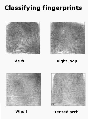
Figure 1: Types of Fingerprints
Every human finger skin has pattern of dark lines (ridges) along with white lines (valleys) between them. Points at which structure of the ridge changes is known as Minutiae. Each human finger has different ridge pattern. These patterns can be Arches (where ridges enter and exit on same sides), Loops (where ridges enter on one side and exit on another) and Whorls (circles or mixtures of different patterns)
Fingerprints can be obtained using two methods – Chemical and Automatic Identification Method
In the former, a surface is sprayed with different chemicals like Cyanoacrylate, Ninhydrin, Magnetic Powder etc. and the finger print patterns can then be lifted using a clear tape. In the latter, the fingerprint images are acquired by different sensors like Capacitive Sensors (obtain pixel value based on capacitance of the fingerprint ridges), Optical Scanners (uses prisms to detect change in reflectance of light by each ridge or valley) and Thermal Scanner (measures differences in temperature over time to create a digital image).
Digital Image Processing in Fingerprint Identification System
Digital Image Processing in Fingerprint Identification System
The basic steps for digital image processing in Fingerprint Identification involves acquiring, storing and analyzing the fingerprint data.
The first step involves acquiring fingerprint images from different sensors like – Optical or Capacitive Sensor. The charge coupled device present in the optical scanner consists of light sensitive diodes which emit electrical signals when illuminated. These tiny dots when hit a target spot form the pixels and an array of pixels form the image. Once the finger is placed on the monitor, the image is acquired by illuminating the ridges of the finger.
The second step involves storing and processing the images using the below given steps.
- Image Segmentation: It involves removal of unwanted features from the acquired image. Procedure followed is Thresholding, wherein the pixels having intensity (gray level value) greater than a particular threshold is considered, whereas those having intensity lesser than the threshold value are removed or deleted.
- Image Normalization: It involves obtaining a uniform intensity pattern for the whole image. This is done so that the image pixels are in a desired range of gray values
- Image Orientation: The image is formed by calculating the orientation at each point. The orientation is in turn determined by calculating the average of vector orthogonal to the gradient of each pixel at X and Y directions.
- Image Filtering: This involves using various techniques like Gabor or Butterworth Filters to remove unwanted noise.
- Image Binarization: This involves conversion of the filtered image to binary image using thresholding technique, to improve the contrast. It utilizes global thresholding technique, wherein pixel value greater than the threshold is set to 1 and pixel value less than the threshold is set to 0.
- Image thinning: This is done to preserve connectivity of the ridges and involves eliminating foreground pixels.
The third step involves analyzing the images, by extracting minutiae details from the processed image and then comparing these details with those of the already stored templates. This is achieved by calculating the crossing number (half of sum of differences) between pair of pixels in aneight-connected neighborhood. This gives a unique identification for each characteristic of the fingerprint.

Fingerprint modules
To achieve fingerprint identification using microcontroller, two types of fingerprint modules can be used – SM630 and R305.
Let us have a brief idea about the two.
A. R305:
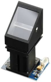
Figure 2: R305 Fingerprint Scanner
- It is a 4 pin, Transistor Transistor Logic (TTL) compatible module, which communicated with Microcontroller through Serial UART communication.While the TD pin connects with the RXD pin of Microcontroller, RD pin connects with the TXD pin of Microcontroller. It supports semiduplex asychronous serial communication with default baud rate of 57600bps (acceptable baud rate can be between 9600 to 115200bps).
The transferred frame is a 10 bit frame with a low level start bit, 8-bit command or data and stop bit. Once powered up, it takes about 500 miliseconds for initialization. The system resources consist of a 512 bytes memory , set as a notepad and two 512 byte character file buffer.
B. SM630:
Figure 3: SM630 Fingerprint Scanner
It is similar to R305 in terms of pin configuration and comunication technique used. Unique features include self developed fingerprint algorithm, self adaptive parameter adjustment mechanism, low cost and power consumption, easy to use and portable integrated design. It consists of 768 fingerprint templates.
Here we are going to use Sunrom’s R305 fingerprint sensor which is connected to an interface board, 1125. It consists of three buttons – ADD, EMPTY and SEARCH. Either these buttons can be used or external commands can be sent to the board from the microcontroller.
In the below circuit, we interface the fingerprint sensor board to the 8051 microcontroller, AT89S51 through serial communication. The result of the identification process is displayed on the LCD.
Once the ADD command is send from the microcontroller, the fingerprint is added to the database and the corresponding ID is sent back to the microcontroller and displayed on the LCD. In case of an error, a code (0xFF) is sent and the error message is displayed on the LCD. Once the EMPTY command is send from the microcontroller, all the added fingerprints are deleted from the database. Response code of 0xCC indicates execution is successful, whereas response code of 0xFF indicates an error.
Once the SEARCH command is send from the microcontroller, the matched ID corresponding to the fingerprint is sent as response code from the microcontroller and the ID is displayed on the LCD. Incase of an error, response code of 0xFF is sent back.
Applications of Fingerprint Identification System
- Crime Scenes: Major application of fingerprint identification system is to identify criminals involved in any crime. One of the foremost evidence searched from the crime scenes are fingerprints on the found items. This helps in finding the criminals based on the fingerprints.
- Organizations: This technique is used to identify members of an organization based on their unique identity number. This makes sure only authorized persons can enter the secured area of the Organization and not any intruder. It also makes count of the attendance of the individual and the time spent inside the place.
- Grocery Stores: This technique is helpful in recognizing and billing an already registered user’s credit or debit card.
Read also
