Jan 28, 2018

Finite-length transmission lines-Part-D

Finite-length transmission lines

A transmission line of infinite length is an interesting abstraction, but physically impossible. All transmission lines have some finite length, and as such do not behave precisely the same as an infinite line. If that piece of 50 Ω "RG-58/U" cable I measured with an ohmmeter years ago had been infinitely long, I actually would have been able to measure 50 Ω worth of resistance between the inner and outer conductors. But it was not infinite in length, and so it measured as "open" (infinite resistance).
Nonetheless, the characteristic impedance rating of a transmission line is important even when dealing with limited lengths. An older term for characteristic impedance, which I like for its descriptive value, is surge impedance. If a transient voltage (a "surge") is applied to the end of a transmission line, the line will draw a current proportional to the surge voltage magnitude divided by the line's surge impedance (I=E/Z). This simple, Ohm's Law relationship between current and voltage will hold true for a limited period of time, but not indefinitely.
If the end of a transmission line is open-circuited -- that is, left unconnected  the current "wave" propagating down the line's length will have to stop at the end, since electrons cannot flow where there is no continuing path. This abrupt cessation of current at the line's end causes a "pile-up" to occur along the length of the transmission line, as the electrons successively find no place to go. Imagine a train traveling down the track with slack between the rail car couplings: if the lead car suddenly crashes into an immovable barricade, it will come to a stop, causing the one behind it to come to a stop as soon as the first coupling slack is taken up, which causes the next rail car to stop as soon as the next coupling's slack is taken up, and so on until the last rail car stops. The train does not come to a halt together, but rather in sequence from first car to last:

A signal propagating from the source-end of a transmission line to the load-end is called an incident wave. The propagation of a signal from load-end to source-end (such as what happened in this example with current encountering the end of an open-circuited transmission line) is called a reflected wave.
When this electron "pile-up" propagates back to the battery, current at the battery ceases, and the line acts as a simple open circuit. All this happens very quickly for transmission lines of reasonable length, and so an ohmmeter measurement of the line never reveals the brief time period where the line actually behaves as a resistor. For a mile-long cable with a velocity factor of 0.66 (signal propagation velocity is 66% of light speed, or 122,760 miles per second), it takes only 1/122,760 of a second (8.146 microseconds) for a signal to travel from one end to the other. For the current signal to reach the line's end and "reflect" back to the source, the round-trip time is twice this figure, or 16.292 μs.
High-speed measurement instruments are able to detect this transit time from source to line-end and back to source again, and may be used for the purpose of determining a cable's length. This technique may also be used for determining the presence and location of a break in one or both of the cable's conductors, since a current will "reflect" off the wire break just as it will off the end of an open-circuited cable. Instruments designed for such purposes are called time-domain reflectometers (TDRs). The basic principle is identical to that of sonar range-finding: generating a sound pulse and measuring the time it takes for the echo to return.
A similar phenomenon takes place if the end of a transmission line is short-circuited: when the voltage wave-front reaches the end of the line, it is reflected back to the source, because voltage cannot exist between two electrically common points. When this reflected wave reaches the source, the source sees the entire transmission line as a short-circuit. Again, this happens as quickly as the signal can propagate round-trip down and up the transmission line at whatever velocity allowed by the dielectric material between the line's conductors.
A simple experiment illustrates the phenomenon of wave reflection in transmission lines. Take a length of rope by one end and "whip" it with a rapid up-and-down motion of the wrist. A wave may be seen traveling down the rope's length until it dissipates entirely due to friction:
This is analogous to a long transmission line with internal loss: the signal steadily grows weaker as it propagates down the line's length, never reflecting back to the source. However, if the far end of the rope is secured to a solid object at a point prior to the incident wave's total dissipation, a second wave will be reflected back to your hand:
Usually, the purpose of a transmission line is to convey electrical energy from one point to another. Even if the signals are intended for information only, and not to power some significant load device, the ideal situation would be for all of the original signal energy to travel from the source to the load, and then be completely absorbed or dissipated by the load for maximum signal-to-noise ratio. Thus, "loss" along the length of a transmission line is undesirable, as are reflected waves, since reflected energy is energy not delivered to the end device.
Reflections may be eliminated from the transmission line if the load's impedance exactly equals the characteristic ("surge") impedance of the line. For example, a 50 Ω coaxial cable that is either open-circuited or short-circuited will reflect all of the incident energy back to the source. However, if a 50 Ω resistor is connected at the end of the cable, there will be no reflected energy, all signal energy being dissipated by the resistor.
This makes perfect sense if we return to our hypothetical, infinite-length transmission line example. A transmission line of 50 Ω characteristic impedance and infinite length behaves exactly like a 50 Ω resistance as measured from one end. If we cut this line to some finite length, it will behave as a 50 Ω resistor to a constant source of DC voltage for a brief time, but then behave like an open- or a short-circuit, depending on what condition we leave the cut end of the line: open or shorted. However, if we terminate the line with a 50 Ω resistor, the line will once again behave as a 50 Ω resistor, indefinitely: the same as if it were of infinite length again:


In essence, a terminating resistor matching the natural impedance of the transmission line makes the line "appear" infinitely long from the perspective of the source, because a resistor has the ability to eternally dissipate energy in the same way a transmission line of infinite length is able to eternally absorb energy.
Reflected waves will also manifest if the terminating resistance isn't precisely equal to the characteristic impedance of the transmission line, not just if the line is left unconnected (open) or jumpered (shorted). Though the energy reflection will not be total with a terminating impedance of slight mismatch, it will be partial. This happens whether or not the terminating resistance is greater or less than the line's characteristic impedance.
Re-reflections of a reflected wave may also occur at the source end of a transmission line, if the source's internal impedance (Thevenin equivalent impedance) is not exactly equal to the line's characteristic impedance. A reflected wave returning back to the source will be dissipated entirely if the source impedance matches the line's, but will be reflected back toward the line end like another incident wave, at least partially, if the source impedance does not match the line. This type of reflection may be particularly troublesome, as it makes it appear that the source has transmitted another pulse.

Review
Characteristic impedance is also known as surge impedance, due to the temporarily resistive behavior of any length transmission line.
A finite-length transmission line will appear to a DC voltage source as a constant resistance for some short time, then as whatever impedance the line is terminated with. Therefore, an open-ended cable simply reads "open" when measured with an ohmmeter, and "shorted" when its end is short-circuited.
A transient ("surge") signal applied to one end of an open-ended or short-circuited transmission line will "reflect" off the far end of the line as a secondary wave. A signal traveling on a transmission line from source to load is called an incident wave; a signal "bounced" off the end of a transmission line, traveling from load to source, is called a reflected wave.
Reflected waves will also appear in transmission lines terminated by resistors not precisely matching the characteristic impedance.
A finite-length transmission line may be made to appear infinite in length if terminated by a resistor of equal value to the line's characteristic impedance. This eliminates all signal reflections.
A reflected wave may become re-reflected off the source-end of a transmission line if the source's internal impedance does not match the line's characteristic impedance. This re-reflected wave will appear, of course, like another pulse signal transmitted from the source.

Read More
Transmission line- 50-Ohm Cable- Part-A
Transmission line-Circuits and the speed of light-Part-B
Transmission line-Characteristic impedance-part-c


Synchronous Motors construction and working principal PART-B

Brush less DC motor- Synchronous Motors-PART-B

Brushless DC motors were developed from conventional brushed DC motors with the availability of solid state power semiconductors. So, why do we discuss brushless DC motors in a chapter on AC motors? Brushless DC motors are similar to AC synchronous motors. The major difference is that synchronous motors develop a sinusoidal back EMF, as compared to a rectangular, or trapezoidal, back EMF for brushless DC motors. Both have stator created rotating magnetic fields producing torque in a magnetic rotor.

Transformer Winding configurations

Winding configurations

Transformers are very versatile devices. The basic concept of energy transfer between mutual inductors is useful enough between a single primary and single secondary coil, but transformers don't have to be made with just two sets of windings. Consider this transformer circuit:

What is Reluctance of motor

Reluctance motor

The variable reluctance motor is based on the principle that an unrestrained piece of iron will move to complete a magnetic flux path with  minimum reluctance, the magnetic analog of electrical resistance.

Transmission line-Characteristic impedance-part-c

Characteristic impedance

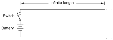
Suppose, though, that we had a set of parallel wires of infinite length, with no lamp at the end. What would happen when we close the switch? Being that there is no longer a load at the end of the wires, this circuit is open. Would there be no current at all?
  

Jan 27, 2018

Concept of Single-phase induction motors

<!-- Global site tag (gtag.js) - Google Analytics Technology for Volt & Current: Single-phase induction motors concept

Single-phase induction motors

A three phase motor may be run from a single phase power source. However, it will not self-start. It may be hand started in either direction, comming up to speed in a few seconds. It will only develop 2/3 of the 3-Φ power rating because one winding is not used.

Ultrasonic Level Sensor Application

Ultrasonic Level Sensor Application 

Ultrasonic Level Sensors and Transmitters
Above ground bulk storage tanks are containers that hold large volumes of liquid and typically

Shape of human brain evolved over time

Mind bender: 

While brain size in Homo sapiens remained largely unchanged over time, the shape gradually became more rounded until achieving its current form, say scientists
Brain shape evolution in Homo sapiens are shown in this combination image—the 300,000 year-old cranium Jebel Irhoud 1 (L) and present day humans (R)—in this undated handout image released on 24 January, 2018. Photo: Reuters

What if cars could read your mind?

Nissan brain-to-vehicle technology

Nissan’s brain-to-vehicle technology will enable autonomous cars to  learn from the brain
The device will measure brain wave activity, which will then be analysed by autonomous systems. Photo: Nissan
The device will measure brain wave activity, which will then be analysed by autonomous systems. Photo:

Jan 26, 2018

15 Best Honeymoon Places In World

 Honeymoon Places In World

couple enjoying winter honeymoon
Being a key ingredient to spice up a relationship, a honeymoon requires an apt amount of intimacy and seclusion to kickstart a newly built bond. Therefore, it

Installing a Load Cell: Best Practices

Best Practice Installation
Each load cell installation is unique. Consult a structural engineer when your application requires very high accuracy, long-term stability, custom specifications, or when using in a varied R&D environment. In order to gain precise weighing results, be sure to use specified load applications for load cells. Load cells have a specified load direction; do not apply side forces, bending or torsional movements on load cells. Inappropriate loading applications will risk reducing the life of load cells, plus distortion of correct measurement results.

Types of Relays: Mechanical, SSR, Internal or External

Types of Relays

What are Relays?

Relays are the control switches that operate with low-powered electrical signals controlling most types of circuits. An example of an ideal relay application is having one electrical signal setup to control several circuits, allowing complete isolation of electricity between the controller and the controlled circuits. 

Improving Safety in Machine Control Systems with Limit Switches

Technology Overview

Control Systems
Imagine a product being moved on a conveyor belt that somehow gets out of place. Not having a limit switch at the edge of the belt to stop the process could cause damage to the product and equipment or pose a safety hazard to the operator and facility. That is the risk for machine control systems with moving mechanical parts. We will discuss different types of limit switches and how they are critical components that serve many purposes including safety and mechanical. 

5 tech trends to keep an eye on in 2018

Basic concept and Calculating of Power Factor

Calculating Power Factor

The angle of this "power triangle" graphically indicates the ratio between the amount of dissipated (or consumed) power and the amount of absorbed/returned power. It also happens to be the same angle as that of the circuit's impedance in polar form. When expressed as a fraction, this ratio between true power and apparent power is called the power factor for this circuit. Because true power and apparent power form the adjacent and hypotenuse sides of a right triangle, respectively, the power factor ratio is also equal to the cosine of that phase angle. Using values from the last example circuit:

Transmission line-Circuits and the speed of light-Part-B

Circuits and the speed of light

Suppose we had a simple one-battery, one-lamp circuit controlled by a switch. When the switch is closed, the lamp immediately lights. When the switch is opened, the lamp immediately darkens:

The Hills From Mumbai!

Beat The Heat 

With the temperature in Mumbai soaring higher each day, one of the best ways to escape the heat is to visit the hill stations around the city. Moreover, these places can be covered over a weekend (preferably a long one), thus saving you precious leaves! All these hill stations are accessible by road, with cabs being easily available and the roads being very scenic. So here’s presenting a list of some of the most-loved hill stations around Mumbai:

Jan 25, 2018

Transmission line- 50-Ohm Cable- Part-A
 I came across a length of coaxial cable with the label "50 ohms" printed along its outer sheath. Now, coaxial cable is a two-conductor cable made of a single conductor surrounded by a braided wire jacket, with a plastic insulating material separating the two. As such, the outer (braided) conductor completely surrounds the inner (single wire)

Jan 24, 2018

Types of specialized motors

1.Shaded pole induction motor

An easy way to provide starting torque to a single phase motor is to embed a shorted turn in each pole at 30o to 60oto the main winding. Typically 1/3 of the pole is enclosed by a bare copper strap. These shading coils produce a time lagging damped flux spaced 30o to 60o from the main field. This lagging flux with the undamped main component, produces a rotating field with a small torque to start the rotor.

Construction & operation of Poly phase motor

Tesla Polyphase Induction Motors

Introduction 

Most AC motors are induction motors. Induction motors are favored due to their ruggedness and simplicity. In fact, 90% of industrial motors are induction motors.
Nikola Tesla conceived the basic principals of the polyphase induction motor in 1883, and had a half horsepower (400 watt) model by 1888. Though he received a million dollars from George Westinghouse for the rights to manufacture this invention, he died penniless.

What is self synchronous motors?

Selsyn (synchro) motors

Normally, the rotor winding of a wound rotor induction motor are shorted out after starting. During starting, resistance may be placed in series with the rotor winding to limit starting current. If these winding are connected to a common starting resistance, the two rotors will remain synchronized during starting. This is useful for printing presses and draw bridges, where two motors need to be synchronized during starting. Once started, and the rotors are shorted, the synchronizing torque is absent. The higher the resistance during starting, the higher the synchronizing torque for a pair of motors. If the starting resistors are removed, but the rotors still paralleled, there is no starting torque. However there is a substantial synchronizing torque. This is a selsyn, which is an abbreviation for "self synchronous".

what is AC commutator motors?

AC commutator motors

AC commutator motors, like comparable DC motors, have higher starting torque and higher speed than AC induction motors. The series motor operates well above the synchronous speed of a conventional AC motor. AC commutator motors may be either single-phase or poly-phase. The single-phase AC version suffers a double line frequency torque pulsation, not present in poly-phase motor. Since a commutator motor can operate at much higher speed than an induction motor, it can output more power than a similar size induction motor. However commutator motors are not as maintenance free as induction motors, due to brush and commutator wear.

Technology for Volt & Current: Honeymoon Places In India

Technology for Volt & Current: Honeymoon Places In India

Step-up and step-down transformers

 Transformers

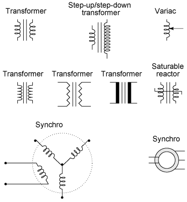
So far, we've observed simulations of transformers where the primary and secondary winding were of identical inductance, giving approximately equal voltage and current levels in both circuits. Equality of voltage and current between the primary and secondary sides of a transformer, however, is not the norm for all transformers. If the inductance of the two winding are not equal, something interesting happens

Circuit Schematic Symbols

CIRCUIT SCHEMATIC SYMBOLS


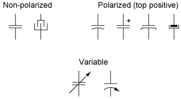
Older electrical schematics showed connecting wires crossing, while non-connecting wires "jumped" over each other with little half-circle marks. Newer electrical schematics show connecting wires joining with a dot, while non-connecting wires cross with no dot. However, some people still use the older convention of connecting wires crossing with no dot, which may create confusion. For this reason, I opt to use a hybrid convention, with connecting wires unambiguously connected by a dot, and non-connecting wires unambiguously "jumping" over one another with a half-circle mark. While this may be frowned upon by some, it leaves no room for interpretational error: in each case, the intent is clear and unmistakable: 


It is very important to keep in mind that the "normal" contact status of a process-actuated switch refers to its status when the process is absent and/or inactive, not "normal" in the sense of process conditions as expected during routine operation. For instance, a normally-closed low-flow detection switch installed on a coolant pipe will be maintained in the actuated state (open) when there is regular coolant flow through the pipe. If the coolant flow stops, the flow switch will go to its "normal" (unactuated) status of closed. A limit switch is one actuated by contact with a moving machine part. An electronic limit switch senses mechanical motion, but does so using light, magnetic fields, or other non-contact means.


Jan 23, 2018

Types of Switches

Switches

In electrical and electronic system, a switch is a device, which can make or break an electrical circuit or we can say that switch is a controlling device, which interrupt the flow of current or direct the flow of current in another direction. Almost all the electrical and electronics systems contain at least one switch, which is used to make the device ON or OFF. In addition, a switch is used to control the circuit operation and user may able to activate or deactivate the whole or certain parts of the connected circuit.

Road trips from Chandigarh to Himalayas

Journey is the Destination

Dan Eldon once said,  “Journey is the Destination“. The landscapes that you witness while travelling to your destination gives you as much peace as the destination itself. The memories that you create while riding on the tough roads rests for the lifetime. There is no reason why should not take a road trip with your friends. India has a lot of scenic road trips to offer, but the trail to the Himalayas steals the show for its scenery that changes its mood very frequently. The Chandigarh city lies very closely to the border of Himachal Pradesh and hence it is quite a famous base to begin your journey towards the majestic Himalayan ranges. Here is the list of best road trips to the Himalayas that you can plan from Chandigarh.

Food of Bihar | 19 Dishes From Bihar Which You Must Try

Food of Bihar

The historically rich land of Bihar is equally famous for the plethora of delicacies that feature in its cuisine. The scrumptious and exotic Bihari dishes are highly capable of tingling the taste bud of every food connoisseur.

Jan 22, 2018

Star-Delta Starter

Introduction:

Most induction motors are started directly on line, but when very large motors are started that way, they cause a disturbance of voltage on the supply lines due to large starting current surges. To limit the starting current surge, large induction motors are started at reduced voltage and then have full supply voltage reconnected when they run up to near rotated speed. Two methods are used for reduction of starting voltage are star delta starting and auto transformer stating.


Jan 21, 2018

Diodes and Rectifiers


diode is an electrical device allowing current to move through it in one direction with far greater ease than in the other. The most common kind of diode in modern circuit design is the semiconductor diode, although other diode technologies exist. Semiconductor diodes are symbolized in schematic diagrams such as Figure below. The term “diode” is customarily reserved for small signal devices, I ≤ 1 A. The term rectifier is used for power devices, I > 1 A.

Vector Group of Transformer

Introduction:

Three phase transformer consists of three sets of primary windings, one for each phase, and three sets of secondary windings wound on the same iron core. Separate single-phase transformers can be used and externally interconnected to yield the same results as a 3-phase unit.

Parallel Operation of Transformers

§  For supplying a load in excess of the rating of an existing transformer, two or more transformers may be connected in parallel with the existing transformer. The transformers are connected in parallel when load on one of the transformers is more than its capacity. The reliability is increased with parallel operation than to have single larger unit. The cost associated with maintaining the spares is less when two transformers are connected in parallel.

Electrical Interview questions

Electrical Interview questions


Q: What is inrush current?
A: Inrush current is the current drawn by a piece of electrically operated equipment when power is first applied. It can occur with AC or DC powered equipment, and can happen even with low supply voltages.

Search This Blog